
Methods and Apparatus for Solid Carbonaceous Materials Synthesis Gas Generation

a technology of solid carbonaceous materials and gas generation, which is applied in the direction of combustible gas production, combustible gas purification/modification, electrochemical generators, etc., can solve the problems high reaction rate, and challenge the perception of uncomplicated design simplicity

Active Publication Date: 2009-05-14
THERMOTEK
View PDF58 Cites 37 Cited by
  • Summary
  • Abstract
  • Description
  • Claims
  • Application Information

AI Technical Summary

Benefits of technology

[0013]The inventive technology relates to methods and apparatus for solid carbonaceous materials synthesis gas generation and embodiments may include the following features: techniques for affirmatively establishing a stoichiometric objectivistic chemic environment in a solid carbonaceous materials gasifier system; techniques for stoichiometrically controlling carbon content in a solid carbonaceous materials gasifier system; techniques for multiple coil carbonaceous reformation in a solid carbonaceous materials gasifier system; techniques for utilizing negatively electrostatically enhanced water species in a solid carbonaceous materials gasifier system; techniques for recycling materials within a solid carbonaceous materials gasifier system; techniques for dominative pyrolytic decomposition of carbonaceous materials within a solid carbonaceous materials gasifier system; techniques for solubilizing contaminants in a solid carbonaceous materials gasifier system; techniques for recycling solubilized contaminants within a solid carbonaceous materials gasifier system; techniques for creating a high energy content select product gas from a solid carbonaceous materi...

Problems solved by technology

However, the biomass input feedstock which is used in gasifiers may challenge perceptions of uncomplicated design simplicity since the feedstock material may represent varying chemical characteristic and physical properties, perhaps as inherent and unique to each individual biomass feedstock material.
The reaction rates are often relatively high; all these variable factors may contribute to the perhaps very complex and complicating nature of gasification processes.
All too often uncontrollable variables may exist that may make gasifiers hard to mass balance control and perhaps to operate satisfactorily within known preventive maintenance procedures, steady-state output constants, and manageable environmental control compliance areas.
In conventional gasification systems, disadvantages often may exist that may create problems in perhaps a variety of areas, including but not limited to areas such as: process control stability related to input feedstock changes, steady state loading, blockage and overall system throughput limitations; slagging potential and challenges; scale-up sizing challenges; moisture limitations; system gas and internal vapor leak challenges; carry-through impurities and contamination challenges, system plugging challenges (such as with excess char, tars or phenols); problems with generated hydrocarbon volatiles and other corrosive sulfur vapor carry-through contaminants being released into produced synthesis gas; decreased BTU energy values in final produced synthesis gas (such as due to excess CO2, N2, or particulate contamination); and the like.
However, these combined double-duty auger system designs may often be plagued with numerous and sporadic mechanical, unpredictable and uncontrollable process (negative) variables.
Auger shaft warpage can cause a high side rotational internal friction wear and can rapidly create stress cracks in an auger-pipe cylinder housing unit.
This can cause constant process pressure variation and can cause vapor leaks.
Excess friction drag can also break shafts.
Further, intermittent carbonaceous material bulk jams can occur whereby the throughput devolatilization reactivity can be either lost or slowed.
While implementing elements may have been available, actual attempts to meet this need to the degree now accomplished may have been lacking to some degree.
This may have been due to a failure of those having ordinary skill in the art to fully appreciate or understand the nature of the problems and challenges involved.
As a result of this lack of understanding, attempts to meet these long-felt needs may have failed to effectively solve one or more of the problems or challenges here identified.

Method used


Image

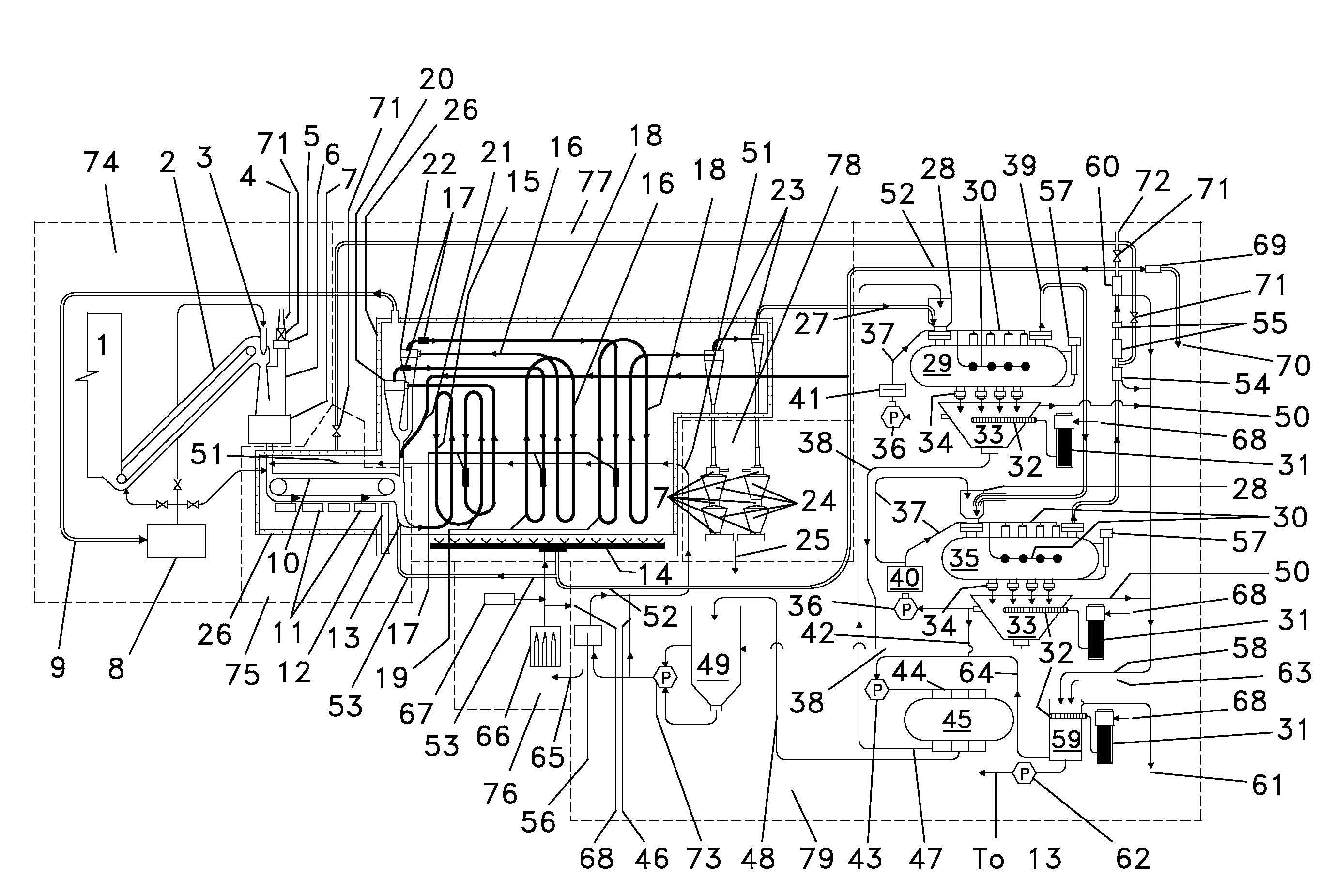
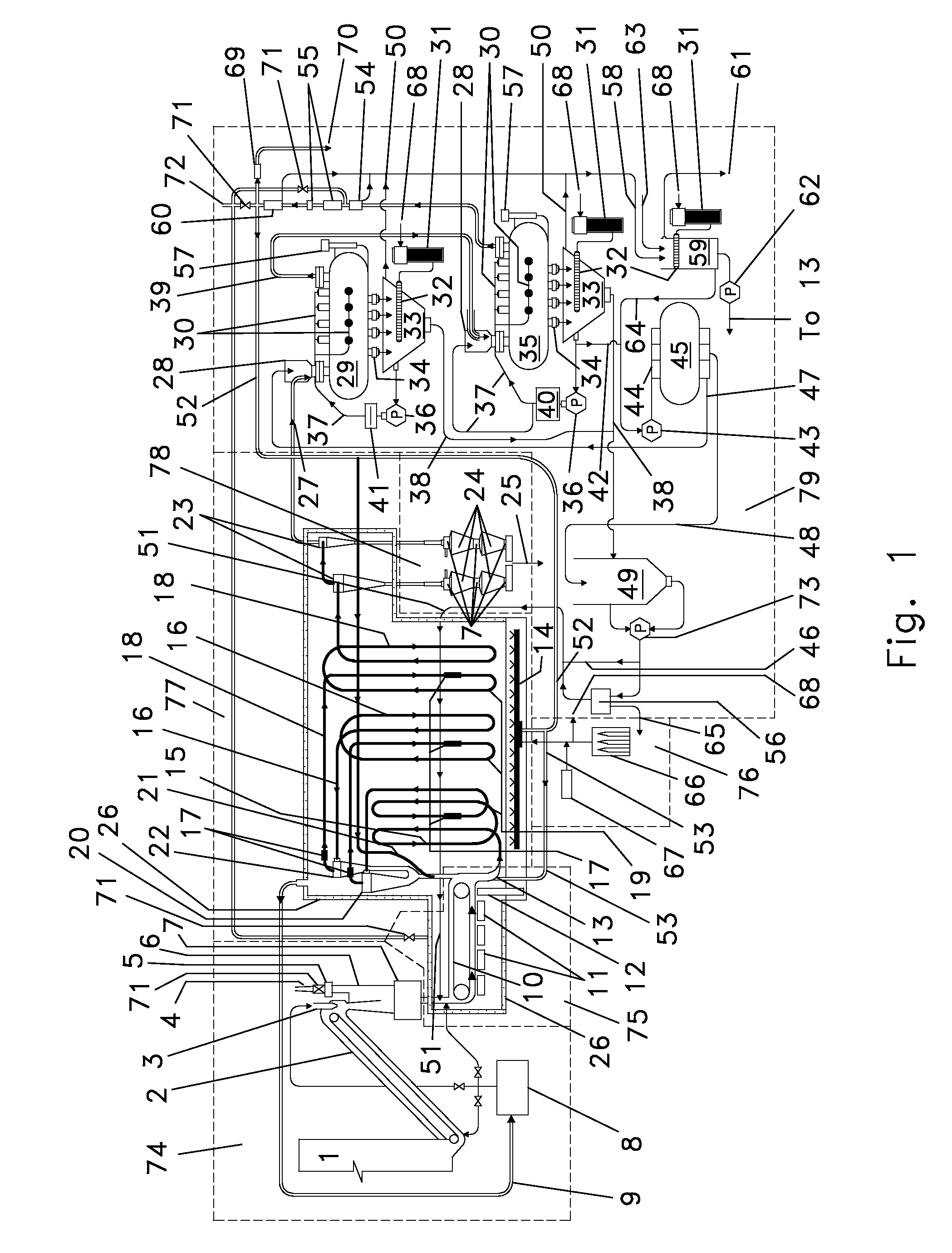
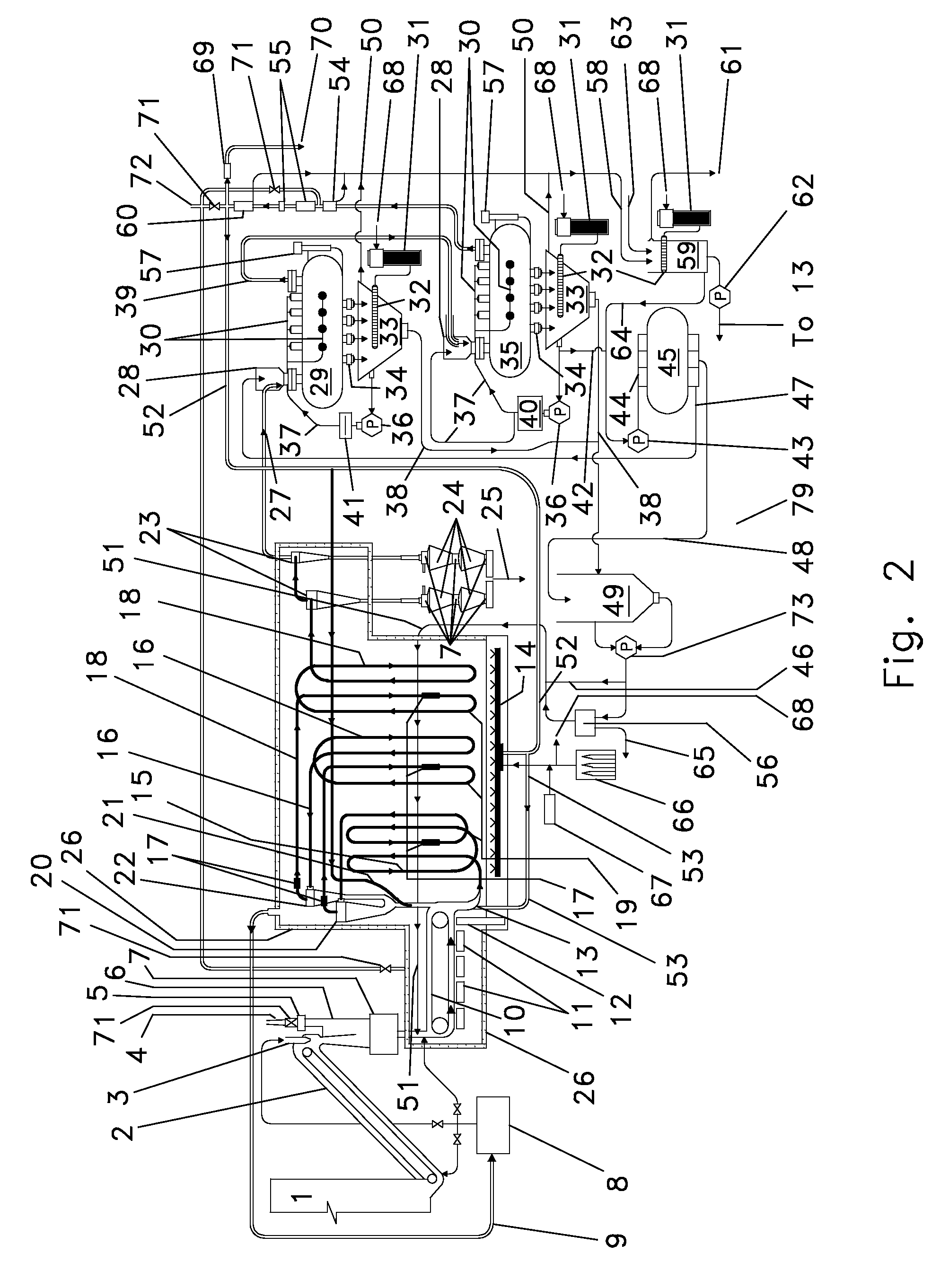
  • Methods and Apparatus for Solid Carbonaceous Materials Synthesis Gas Generation
  • Methods and Apparatus for Solid Carbonaceous Materials Synthesis Gas Generation
  • Methods and Apparatus for Solid Carbonaceous Materials Synthesis Gas Generation

Examples


Embodiment Construction

[0036]The present inventive technology includes a variety of aspects, which may be combined in different ways. The following descriptions are provided to list elements and describe some of the embodiments of the present inventive technology. These elements are listed with initial embodiments, however it should be understood that they may be combined in any manner and in any number to create additional embodiments. The variously described examples and preferred embodiments should not be construed to limit the present inventive technology to only the explicitly described systems, techniques, and applications. Further, this description should be understood to support and encompass descriptions and claims of all the various embodiments, systems, techniques, methods, devices, and applications with any number of the disclosed elements, with each element alone, and also with any and all various permutations and combinations of all elements in this or any subsequent application.

[0037]A soli...


PUM


Abstract

Methods and apparatus may permit the generation of consistent output synthesis gas from highly variable input feedstock solids carbonaceous materials. A stoichiometric objectivistic chemic environment may be established to stoichiometrically control carbon content in a solid carbonaceous materials gasifier system. Processing of carbonaceous materials may include dominative pyrolytic decomposition and multiple coil carbonaceous reformation. Dynamically adjustable process determinative parameters may be utilized to refine processing, including process utilization of negatively electrostatically enhanced water species, process utilization of flue gas (9), and adjustment of process flow rate characteristics. Recycling may be employed for internal reuse of process materials, including recycled negatively electrostatically enhanced water species, recycled flue gas (9), and recycled contaminants. Synthesis gas generation may involve predetermining a desired synthesis gas for output and creating high yields of such a predetermined desired synthesis gas.

Description

TECHNICAL FIELD[0001]The inventive technology described herein relates to gasifier systems utilizing solid carbonaceous materials to generate synthesis gases. More specifically, such gasifier systems may be configured to utilize one or more of a variety of process control parameters, perhaps singly or in combinations, to achieve high degrees of efficiency and control in such synthesis gas generation. The inventive technology may be particularly suited to receive a great variety of solid carbonaceous materials as feedstock for the gasifier system and to generate synthesis gases of variable types suitable for a great variety of subsequent applications.BACKGROUND[0002]Pyrolysis, or controlled heating of feedstock in the absence of oxygen, resulting in thermal decomposition of the feedstock fuel into volatile gases and solid carbon material by-product, was first practiced on a commercial scale in 1812, when a city gas company in London started the production of town gas applications.[00...

Claims


Application Information

Patent Timeline
IPC IPC(8): C10J3/48C10J3/46C10J1/207
CPCC10J3/66C10J2300/0903C10J2300/0916C10J2300/093C02F1/32C10J2300/0946C10K1/101Y02E50/32C10B1/10C10J2300/0943C10J2300/1215Y02E20/18Y02E50/30Y02E50/10C10J3/20C10B47/18Y02P20/145
Inventor JOHNSON, DENNIS E.J.ABRAMOV, GRIGORI A.KLEINKE, RICHARD A.WILEY, MARCUS A.
Owner THERMOTEK
Learn More