Dye-sensitized solar cell using conductive fiber electrode

a technology of conductive fiber and solar cell, applied in the field of solar cells, can solve the problems of inability to manufacture and utilize dye-sensitized solar cells, inability to bendable dye-sensitized solar cells, and reduced glass flexibility, so as to achieve the effect of increasing flexibility and formability of dye-sensitized solar cells and significantly improving energy conversion efficiency

Inactive Publication Date: 2009-05-21
ELECTRONICS & TELECOMM RES INST
View PDF5 Cites 14 Cited by
  • Summary
  • Abstract
  • Description
  • Claims
  • Application Information

AI Technical Summary

Benefits of technology

[0011]The present invention provides a dye-sensitized solar cell having great flexibility, intensity, and energy conversion efficiency, and whose mass manufacturing process is easy.
[0023]Since a conductive fiber is used as a conductive layer of a semiconductor electrode, the contact surface between the conductive fiber and the nano-particle semiconductor oxide layer is increased, thus making the transition path of electrons short, and consequently, more light can be absorbed by making the electrode layer thick. Thus the energy conversion efficiency can be increased significantly. Also, the flexibility and the formability of the dye-sensitized solar cell can be increased based on the flexibility and formability of the conductive fiber which forms the electrode layer.

Problems solved by technology

However, a conventional dye-sensitized solar cell includes an anode formed of a glass substrate, on a surface of which a conductive layer is formed, and when a nano-particle semiconductor oxide is attached / sintered thereon, the flexibility of glass is decreased, and thus, a bendable dye-sensitized solar cell cannot be realized.
Thus, manufacturing and utilizing dye-sensitized solar cells have been difficult.
However, according to this patent application, when the metal substrate is thin, the dye-sensitized solar cell is sufficiently flexible but the intensity thereof is decreased; and when the metal substrate is thick, the flexibility of the dye-sensitized solar cell is not great.

Method used


Image

  • Dye-sensitized solar cell using conductive fiber electrode
  • Dye-sensitized solar cell using conductive fiber electrode
  • Dye-sensitized solar cell using conductive fiber electrode

Examples


embodiment

[0040]Referring to FIGS. 2 and 4, the current embodiment of the present invention will be described in more detail.

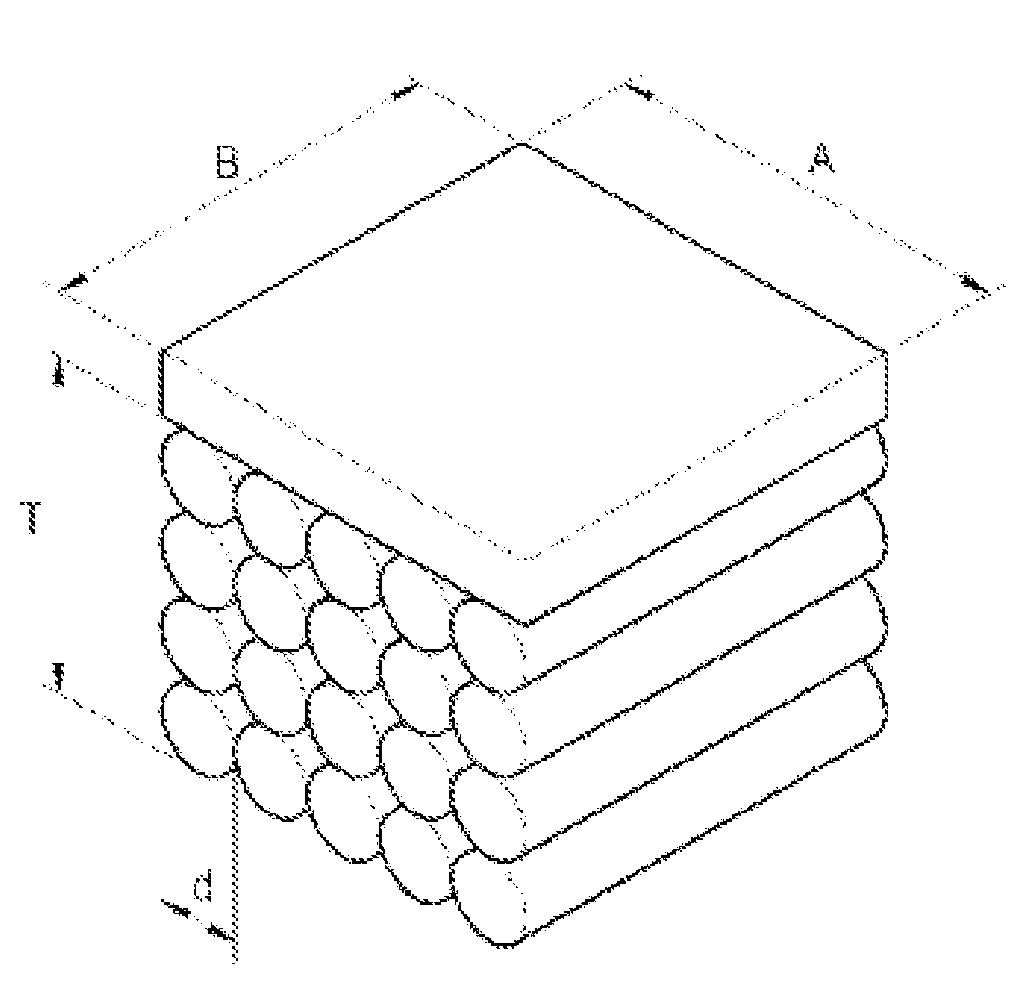
[0041]The semiconductor electrode 200 according to the current embodiment of the present invention has a structure in which a conductive layer, in which glass fibers that are surface-treated with ITO or SnO2 and have a diameter of 10-100 μm are stacked, is covered with a nano-particle semiconductor oxide layer 212 formed of TiO2 having a size of about 15-25 nm. Dye molecules 214 formed of ruthenium (Ru) complex compound are adsorbed on a surface of the nano-particle semiconductor oxide layer 212. The semiconductor electrode 200 is covered by an electrolyte solution 230. The electrolyte solution 230 may be an iodine based oxidization-reduction liquid electrolyte, for example, an I3− / I−electrolyte solution in which 1-vinyl-3-hexyl-imidazolium iodide of 0.7 M, Lil of 0.1 M, and iodine (I2) of 40 mM are dissolved in 3-methoxypropionitrile.

[0042]The counter electrode 300 may...


PUM


Abstract

Provided is a dye-sensitized solar cell including a flexible electrode. The dye-sensitized solar cell includes: first and second electrodes facing each other, and an electrolyte layer interposed between the first and second electrodes, wherein the first electrode comprises a structure formed of conductive fibers, a nano-particle semiconductor oxide layer formed on a surface of the structure of the conductive fibers, and dye molecules adsorbed in the nano-particle semiconductor oxide layer.

Description

CROSS-REFERENCE TO RELATED PATENT APPLICATION[0001]This application claims the benefit of Korean Patent Application No. 10-2007-0118065, filed on Nov. 19, 2007 in the Korean Intellectual Property Office, the disclosure of which is incorporated herein in its entirety by reference.BACKGROUND OF THE INVENTION[0002]1. Field of the Invention[0003]The present invention relates to a solar cell, and more particularly, to a dye-sensitized solar cell having an electrode formed of a new material, so that the dye-sensitized solar cell has improved flexibility, processability, and efficiency.[0004]The present invention is derived from a research project supported by the Information Technology (IT) Research & Development (R&D) program of the Ministry of Information and Communication (MIC) [2009-S-006-02, Component Module for Ubiquitous Terminal].[0005]2. Description of the Related Art[0006]A dye-sensitized solar cell is a new type of a low-cost solar cell that was developed in Switzerland in 1991...

Claims


Application Information

Patent Timeline
Patent Type & Authority Applications(United States)
IPC IPC(8): H01L31/00
CPCH01G9/2031Y02E10/542H01G9/2086H01G9/2059Y02P70/50H01L31/0224H01L31/04
Inventor PAK, HUNKYUNLEE, SEUNGYUPKANG, MANGUJUN, YONGSEOKYUN, HOGYEONGPARK, JONG HYEOKKIM, JONGDAE
Owner ELECTRONICS & TELECOMM RES INST
Why Eureka
Try Eureka