

Grid polarizing film, method for producing the film, optical laminate, method for producing the laminate, and liquid crystal display
a grid polarizer and film manufacturing method technology, applied in the direction of polarizing elements, paper/cardboard containers, instruments, etc., can solve the problems of difficult to control the width, shape and the like of cracks, and difficult to achieve uniform optical characteristics in a plane, and achieve easy to obtain a lengthy grid polarizer film, improve the use efficiency of light, and improve the effect of polarized light isolation performan
- Summary
- Abstract
- Description
- Claims
- Application Information
AI Technical Summary
Benefits of technology
Problems solved by technology
Method used
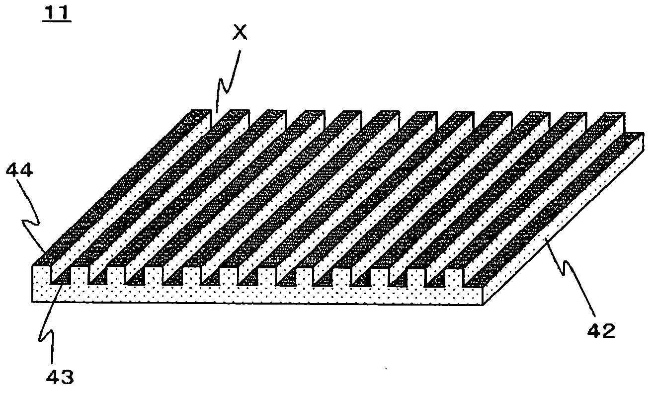
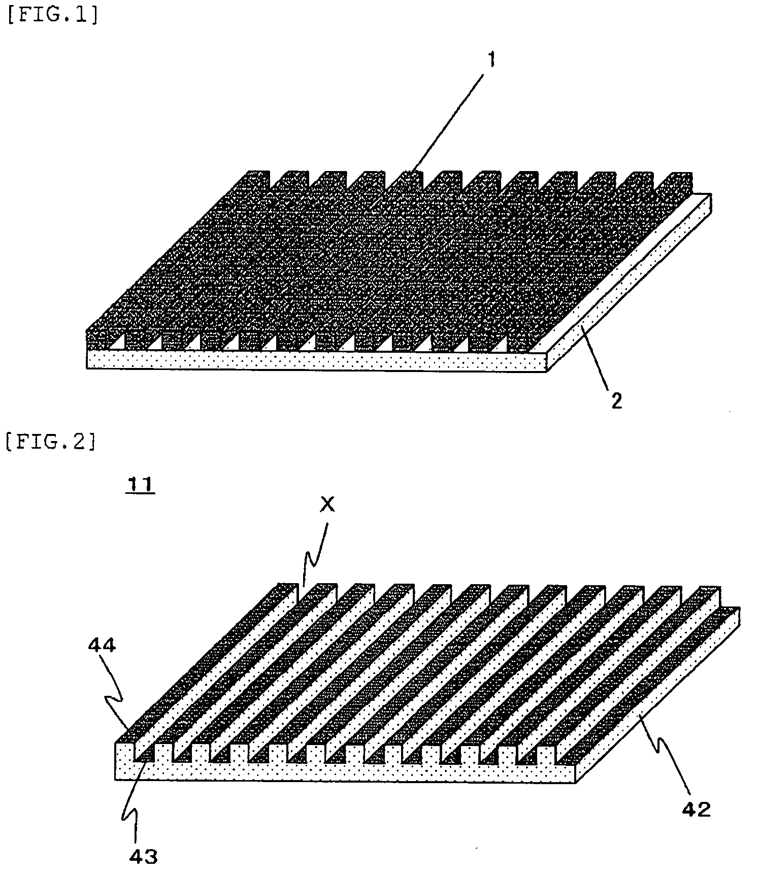
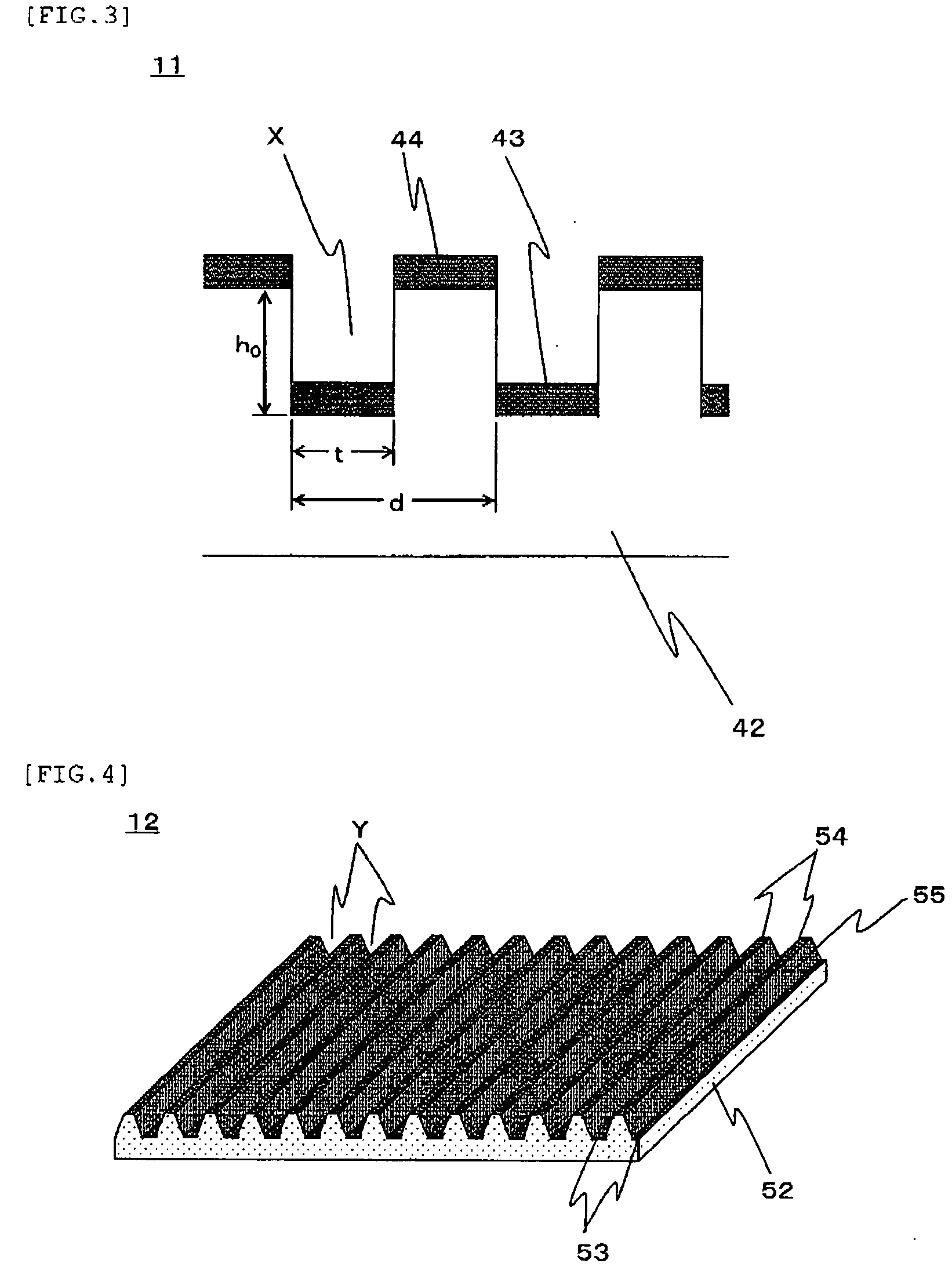
Image

Examples
example 1
Manufacture of Lengthy Grid Polarizer Film I
[0139]On a surface of 0.2 mm×1 mm of rectangular single-crystal diamond with the dimension of 0.2 mm×1 mm×1 mm brazed to a shank of 8 mm×8 mm×60 mm made by SUS, focused ion beam processing using argon ion beam was carried out by using a focused ion beam processing device (made by Seiko Instruments, SMI3050) so as to engrave grooves with the width of 0.1 μm and the depth of 0.1 μm with a pitch of 0.2 μm in parallel with a side with the length of 1 mm so as to fabricate a cutting tool comprising 1000 straight projections (ridges) with the width of 0.1 μm and the height of 0.1 μm with a pitch of 0.2 μm.
[0140]On the entire surface of the peripheral face of a roll made by cylindrical stainless steel SUS430 with the diameter of 200 mm and the length of 150 mm, nickel-phosphorous electroless plating with the thickness of 100 μm was applied and then, using the cutting tool fabricated in advance with straight projections and a precision cylindrical...
example 2
Manufacture of Lengthy Grid Polarizer Film 2
[0147]A lengthy grid polarizer film 2 was obtained similarly to the example 1 except that a base film B made of polycarbonate resin (Teijin chemicals ltd., Panlite K-1300Y) fabricated by a casting method instead of the base film A. The average in-plane retardation at the wavelength of 550 nm of the base film B was 8 nm, fluctuation of the in-plane retardation in the width direction and longitudinal direction was ±2 nm and fluctuation of the optical axis was ±8°.
[0148]The absorbing-type polarizing film obtained in the example 1 and the above lengthy grid polarizer film 2 were wound out from the roll respectively, while the lengthy grid polarizer film was laminated on one face of the absorbing-type polarizing film through an adhesive layer using an urethane adhesive, a lengthy protective film made of triacetylcellulose was laminated on the another side of the absorbing-type polarizing film through an adhesive layer using the urethane adhesiv...
example 3
Manufacture of Lengthy Grid Polarizer Film 3
[0157]On a face of 0.2 mm×1 mm of rectangular single-crystal diamond with the dimension of 0.2 mm×1 mm×1 mm brazed to a shank of 8 mm×8 mm×60 mm made by SUS, focused ion beam processing using argon ion beam was carried out by using a focused ion beam processing device (made by Seiko Instruments, SMI3050) so as to engrave grooves with the width of 50 nm and the height of 60 nm with a pitch of 130 nm in parallel with a side with the length of 1 mm so as to fabricate a cutting tool comprising straight projections with the width of 80 nm and the height of 60 nm with a pitch of 130 nm.
[0158]On the entire surface of the peripheral face of a roll made by cylindrical stainless steel SUS430 with the diameter of 80 mm and the length of 125 mm, nickel-phosphorous electroless plating with the thickness of 100 μm was applied and then, using the cutting tool fabricated in advance with straight projections and a precision cylindrical grinding machine (ma...
PUM
| Property | Measurement | Unit |
|---|---|---|
| temperature | aaaaa | aaaaa |
| diameter | aaaaa | aaaaa |
| refractive index | aaaaa | aaaaa |
Abstract
Description
Claims
Application Information