Forged austenitic stainless steel alloy components and method therefor

Inactive Publication Date: 2009-05-21
GENERAL ELECTRIC CO
View PDF9 Cites 17 Cited by
  • Summary
  • Abstract
  • Description
  • Claims
  • Application Information

AI Technical Summary

Benefits of technology

[0006]The present invention provides a forgeable austenitic stainless steel alloy and forging process capable of producing forged components that exhibit mechanica

Problems solved by technology

Austenitic stainless steel alloys such as type 304, 347, 316, 321, etc., have stable austenitic microstructures at room temperature, but can suffer from l

Method used


Image

  • Forged austenitic stainless steel alloy components and method therefor
  • Forged austenitic stainless steel alloy components and method therefor

Examples


Embodiment Construction

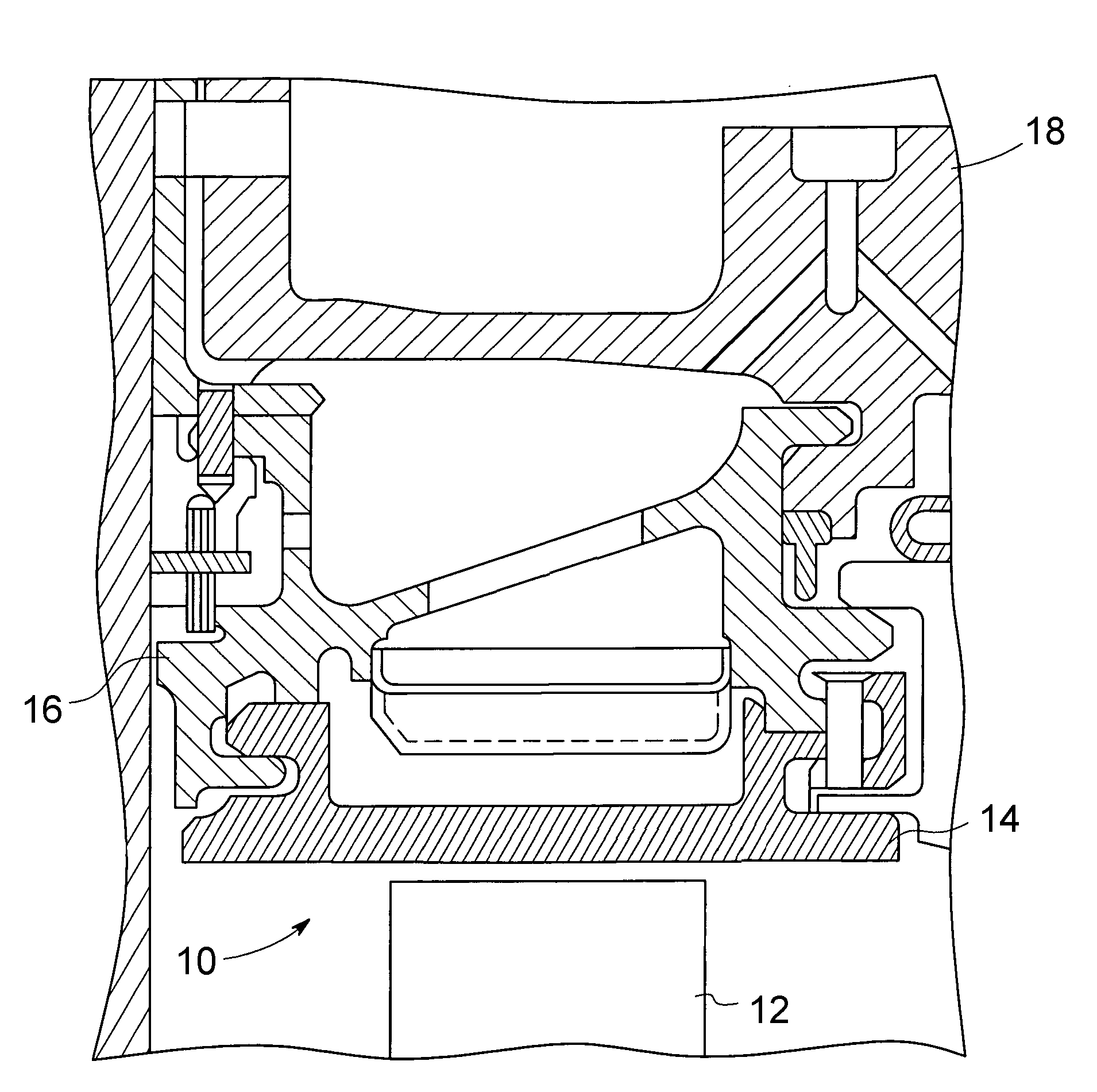
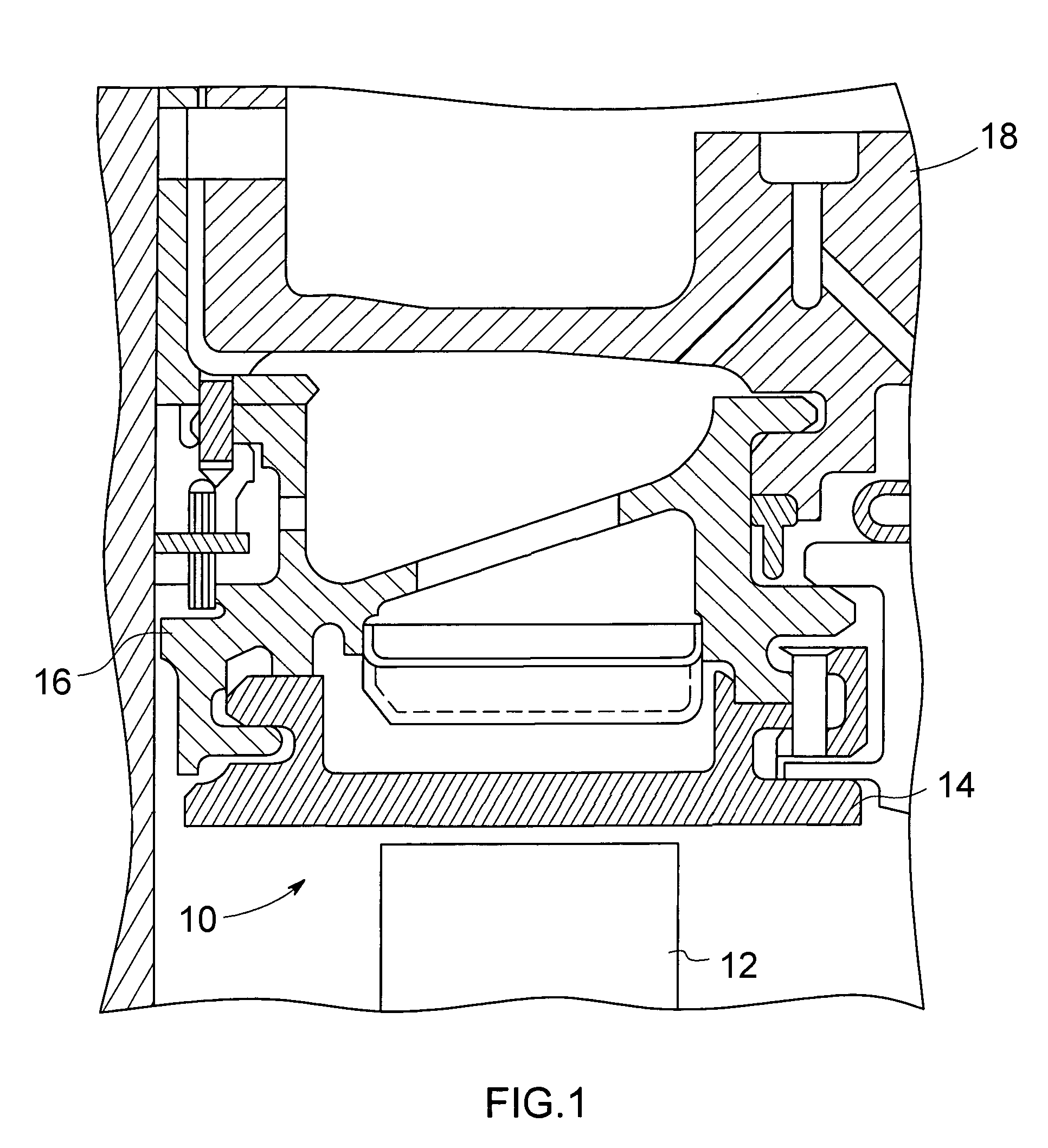
[0012]FIG. 1 represents a fragmentary view of a longitudinal cross section through a turbine section of a gas turbine engine, and shows components of a shroud assembly 10 within the turbine section. As known, the shroud assembly 10 circumscribes the turbine rotor (not shown) of the gas turbine engine, such that a turbine blade 12 is shown in proximity to the shroud assembly 10. The blade 12 is one of multiple blades mounted on the rotor, which rotates coaxially within the stationary shroud assembly 10. The shroud assembly 10 comprises a shroud 14 and a hanger 16 by which the shroud 14 is supported. The radially inward face of the shroud 14 faces the blade tips of the turbine rotor and minimizes the gas leakage path between the shroud assembly 10 and the rotor blade tips. The shroud 14 and its hanger 16 are preferably fabricated as multiple individual sections, with shroud sections circumferentially adjoining each other to define a substantially continuous annular shape that surround...


PUM

PropertyMeasurementUnit
Temperatureaaaaaaaaaa
Fractionaaaaaaaaaa
Fractionaaaaaaaaaa

Abstract

A forgeable austenitic stainless steel alloy and forging process capable of producing forged components that exhibit mechanical and environmental properties and metallurgical stability suitable for use in thermally and chemically hostile environments, such as the environment of a component of a gas turbine engine shroud assembly. The alloy contains, by weight, 18.0 to 22.0% chromium, 8.0 to 14.0% nickel, 4.0 to 7.0% manganese, 0.4 to 0.6% silicon, at least 0.2 up to 1.0% nitrogen, at least 0.05 up to 0.075% carbon; up to 0.3% molybdenum, up to 1.0% niobium, up to 0.2% cobalt, up to 4.5% aluminum, up to 0.1% boron, up to 0.1% vanadium, up to 1.0% tungsten, and up to 5.0% copper, with the balance iron and incidental impurities.

Description

BACKGROUND OF THE INVENTION[0001]The present invention generally relates to stainless steel alloys and their processing. More particularly, this invention relates to a forgeable austenitic stainless steel alloy and forgings formed therefrom that have desirable mechanical and environmental properties and very stable microstructures over long periods of time at operating temperatures seen by internal components of gas turbine engines.[0002]Various alloys have been considered and used for high-temperature components of turbomachinery, with individual alloys being chosen on the basis of the particular demands of the application. Shrouds, which surround the outer blade tips within the turbine section of a turbomachine, such as a gas turbine engine, require high temperature strength and ductility, as well as good low cycle fatigue and oxidation properties. Furthermore, to maintain their performance at temperatures exceeding 700° C. for extended periods of time, e.g., in excess of 50,000 o...

Claims


Application Information

Patent Timeline
IPC IPC(8): C22C38/52C21D8/00C22C30/00
CPCC21D1/26C21D6/004C21D6/005C21D7/13C21D9/0068C21D2211/001F05D2300/171C22C38/001C22C38/02C22C38/48C22C38/58F01D9/06F05D2230/25C21D2211/004C22C38/40
Inventor GOLLER, GEORGE ALBERT
Owner GENERAL ELECTRIC CO
Why Eureka
Try Eureka