Method of fabrication electrodes with low contact resistance for batteries and double layer capacitors

a double-layer capacitor and electrode fabrication technology, applied in the direction of electrolytic capacitors, cell components, electrochemical generators, etc., can solve the problems of low rc constant value, low contact resistance, and insufficient resistance of carbon cloth used in such electrodes, so as to achieve low cost and still effective effect of low contact resistan

Inactive Publication Date: 2009-05-21
ENERIZE CORP
View PDF2 Cites 24 Cited by
  • Summary
  • Abstract
  • Description
  • Claims
  • Application Information

AI Technical Summary

Benefits of technology

[0007]An object of the present invention is to develop a low-cost but still effective method of fabricating the electrodes for batteries, double-layer capacitors or hybrid devices with low contact resistance between the metal current collector and carbon-containing electrode. An example of hybrid device is supercapacitor/Li-ion battery. Another object of the present invention to develop a gradient electrode material, which comprises at least two different layers: the

Problems solved by technology

However, the carbon cloth used in such electrodes tends to be somewhat costly.
And as an electrode material, carbon cloth is inherently too thick (300 microns or more) to provide the very low resistivi

Method used


Image

  • Method of fabrication electrodes with low contact resistance for batteries and double layer capacitors
  • Method of fabrication electrodes with low contact resistance for batteries and double layer capacitors
  • Method of fabrication electrodes with low contact resistance for batteries and double layer capacitors

Examples


example 1

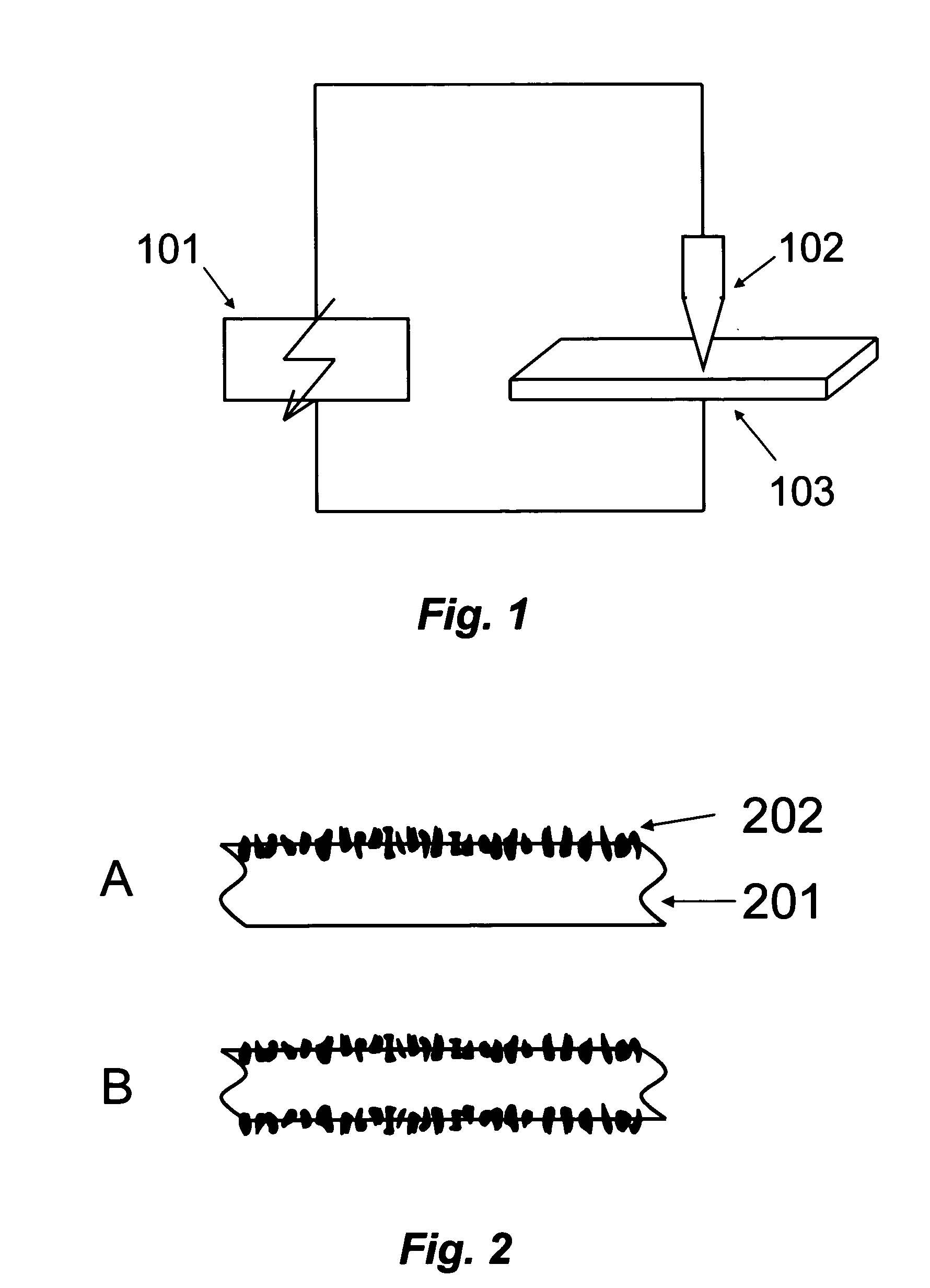
[0030]Aluminum foil with the thickness 20 microns was pressed with a copper plate with the frame from stainless steel with a rectangular window 35×45 mm. With the help of an electro spark device, which included a positive electrode from graphite rod and negative electrode of aluminum foil, the aluminum foil was doped with the particles of graphite over the windows of the frame. The current of the process was 0.6 A. The duration was 6 minutes. As a result, a layer of graphite was fused into the surface of the aluminum. The thickness of this graphite layer was 3-5 microns. Onto the aluminum current collector with the graphite layer that was fused into the surface of the aluminum, a suspension of nano-porous carbon powder with PVDF binder was coated. The concentration of the binder was 10%. The method of coating was casting. After drying, and following forge-rolling, the thickness of the nano-porous carbon was approximately 100 microns. The resistance of electrode that was fabricated b...

example 2

[0031]Aluminum foil having a thickness of 60 microns was passed through rolls several times with emery paper to roughen the surface. Thereafter, the aluminum foil was pressed with a copper plate with the frame of stainless steel, with a rectangular window 35×45 mm. Using an electro-spark device that included a positive electrode comprising a graphite rod and a negative electrode that comprised said aluminum foil, the roughened aluminum foil was doped with particles of graphite over the windows of the frame. The electrical current of the doping process was between 0.6 A and 1.0 A. The duration of the process was 7 minutes. The resulting layer of the graphite was fused into the surface of the aluminum. The thickness of this graphite layer was 3-5 microns.

[0032]A suspension of nano-porous carbon powder with PTFE binder was disposed onto the aluminum current collector with the graphite layer that was fused into the surface of the aluminum. The concentration of the binder was 7%. The met...

example 3

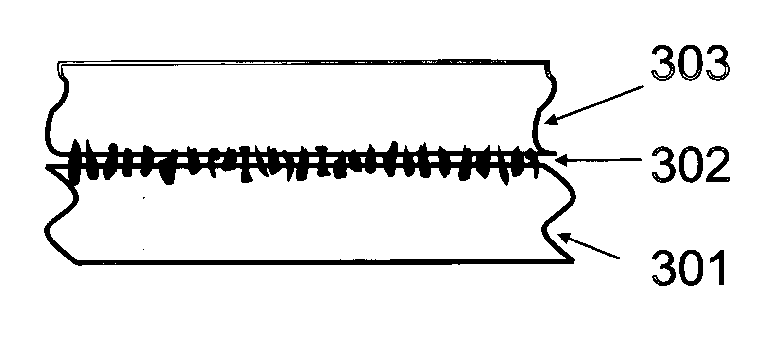
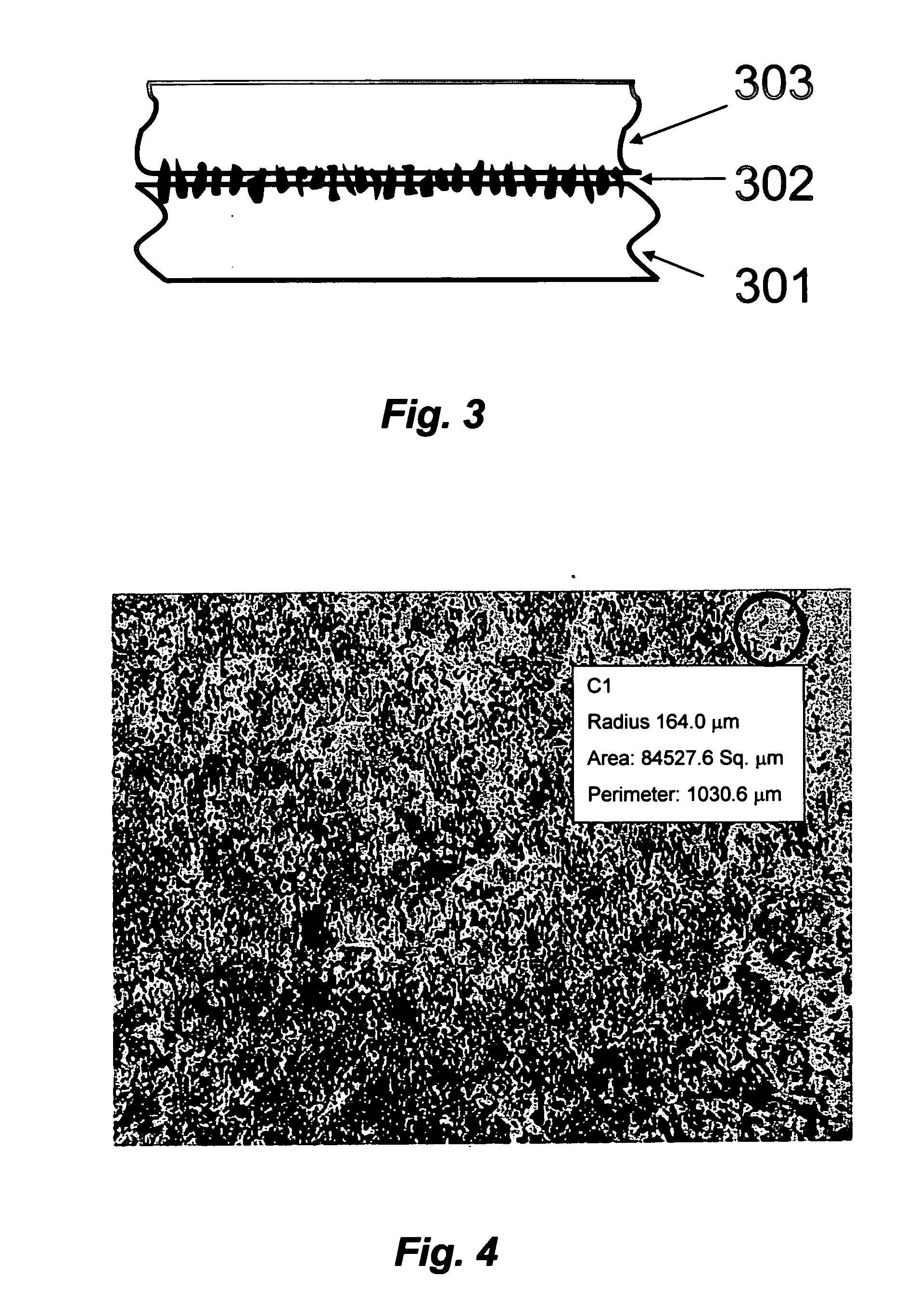
[0033]The surface of an aluminum foil strip with thickness 60 micron was treated as described in Example 2. Thereafter, the aluminum foil was pressed with a copper plate and the surface of the aluminum foil was doped as described in Examples 1 and 2. The current of the doping process was between 0.6 A and 1.0 A. The duration of the process was 8 minutes. The thickness of the resulting graphite layer that was fused into the surface of the aluminum was 3-5 micron. Thereafter, a thin layer (1-2 micron) of acetylene black was disposed onto the surface. Thereafter, onto the fabricated surface that included aluminum and two layers of carbon, a suspension of nano-porous carbon powder with PTFE binder (7%) was coated using the method of forge-rolling. The resulting thickness of the nano-porous carbon was approximately 100 microns. The resistance of the electrode that was fabricated by the method describe above was measured. The method used for the resistance measurement is described below. ...


PUM

PropertyMeasurementUnit
Diameteraaaaaaaaaa
Electrical conductivityaaaaaaaaaa
Electrical resistanceaaaaaaaaaa

Abstract

The present invention is a low-cost method for fabricating electrodes for batteries, electric double-layer capacitors (EDLC or supercapacitors) and hybrid electrical energy storage devices. for which by low contact resistance between the metal current collector and carbon-containing electrode enhances performance. The electrodes comprise at least two layers. The first layer is a highly conductive carbon material, such as graphite, fused into the metal current collector. The second layer is a polarizing carbon-containing electrode typically comprising a nanoporous carbon powder pressed or rolled with a binder, or a composite that includes active materials (for example oxides, sulfides), binder and conductive additives such as carbon, black. The method provides electrodes with low interface resistance, which lowers the overall internal electrical resistance of the battery or EDLC devices in which they are used and allows it to deliver increased power.

Description

CROSS-REFERENCE TO RELATED APPLICATIONS[0001]This application claims priority of PCT # WO 2007 / 116244 A2 filed 23 Jun., 2005FEDERALLY SPONSORED RESEARCH[0002]NoneSEQUENCE LISTING[0003]NoneFIELD OF THE INVENTION[0004]This invention relates to a method of fabricating the electrodes for batteries and double-layer capacitors (EDLC). More particularly, the invention relates to a method of fabricating electrodes for batteries and double-layer capacitors or hybrid devices with low contact (or interfacial) resistance between the electrode material and metal current collector.BACKGROUND[0005]Double-layer capacitors, also referred to as electrochemical double layer capacitors (EDLC) or supercapacitors, are energy storage devices that are characterized by very low internal resistance in order to provide the high power output. One way of improving EDLC devices is to reduce all contributions to the internal resistance. These include the contact resistance between the polarizing nanoporous carbon...

Claims


Application Information

Patent Timeline
IPC IPC(8): H01M4/00H01M6/00
CPCH01G9/016Y10T29/49108H01G11/26H01G11/28H01G11/38H01G11/42H01G11/46H01G11/86H01M4/621H01M4/624H01M4/625H01M4/661H01M4/667H01M12/005Y02E60/13H01G9/058H01G11/22H01G11/68H01G11/74Y02E60/10
Inventor SHEMBEL, ELENA
Owner ENERIZE CORP
Why Eureka
Try Eureka