Separation of water from hydrocarbons

a technology of hydrocarbon fuel and water, applied in the field of method, can solve the problems of accelerating corrosion, exacerbated problems of product quality control, and excessive amounts of water frequently adversely affecting the properties and quality of hydrocarbon fuels

Inactive Publication Date: 2009-05-28
EXXON RES & ENG CO
View PDF4 Cites 26 Cited by
  • Summary
  • Abstract
  • Description
  • Claims
  • Application Information

AI Technical Summary

Problems solved by technology

Excess amounts of water frequently adversely affect the properties and quality of hydrocarbon fuels, for example, by creating haze in fuels which would otherwise be clear, accelerating rust and other forms of corrosion on containers and equipment, and by the formation of ice crystals at low temperatures which may lead to plugging of filters and other equipment, for example, fuel injectors.
Water may also contain contaminants such as acids which may lead to accelerated corrosion.
Products sold in cold climates are particularly subject to problems arising from the freezing of water and the consequence formation of ice crystals at temperatures below freezing, the problems of product quality control are therefore exacerbated in such climates.
The production of petroleum hydrocarbons from subterranean formations may also result in hydrocarbon streams which are contaminated by water, either alone or mixed with other contaminants.
While water, e.g. brine, may normally be readily separated from liquid crudes, problems may be encountered with the separation of water from other produced fluids, for example, natural gas condensates which are relatively light, low boiling hydrocarbon fractions produced from natural gas wells.
One instance of this problem is in the production of natural gas which has a relatively high water content which leads to undesirable hydrate formation; hydrates normally require removal prior to the shipping of the gas because of their propensity to plug equipment and flowlines.
Large quantities of water which are encountered in some gas fields, especially when low ambient temperatures are prevalent, may however make normal processing techniques ineffective or of limited utility.
While chemical methods may be used to remove water from the main body of the fuel, they have generally received less commercial acceptance on the large scale used in refinery operations because of the cost factor.
Chemical methods, including salt drying, require the replacement or regeneration of the reagents used in the process and the reagents themselves and their products formed by interaction with the water frequently introduce their own complications in subsequent processing.
In addition, the properties of the system such as drop size, curvature of the liquid / liquid interface, temperature, concentration gradients and vibrations may also affect the effectiveness of the coalescence.
While electrostatic precipitators may be effective on such emulsions down to interfacial tensions below 10 dyne / cm, their use is rather less favored than the relatively cheaper coalescence method.
Frequent changes of the cartridge material in the coalescers may obviate this problem but the increased labor and disposal costs associated with frequent cartridge change out are undesirable as is the continued need to monitor the quality of the product to ensure that appropriate specifications are being met.
The use of various polymeric materials such as phenolic or acrylic resins which act primarily as binding agents for glass fiber packings may be effective to reduce disarming of coalescers to a significant extent, but the problem remains.
Regardless of the details of the coalescence / separation techniques used one problem that remains, particularly in cold climates, is the problem of icing.
Accordingly, regardless of the potential for utilizing the coalescence / separation technique, problems arising from the presence of water in the feed still remain.

Method used


Image

  • Separation of water from hydrocarbons
  • Separation of water from hydrocarbons

Examples


Embodiment Construction

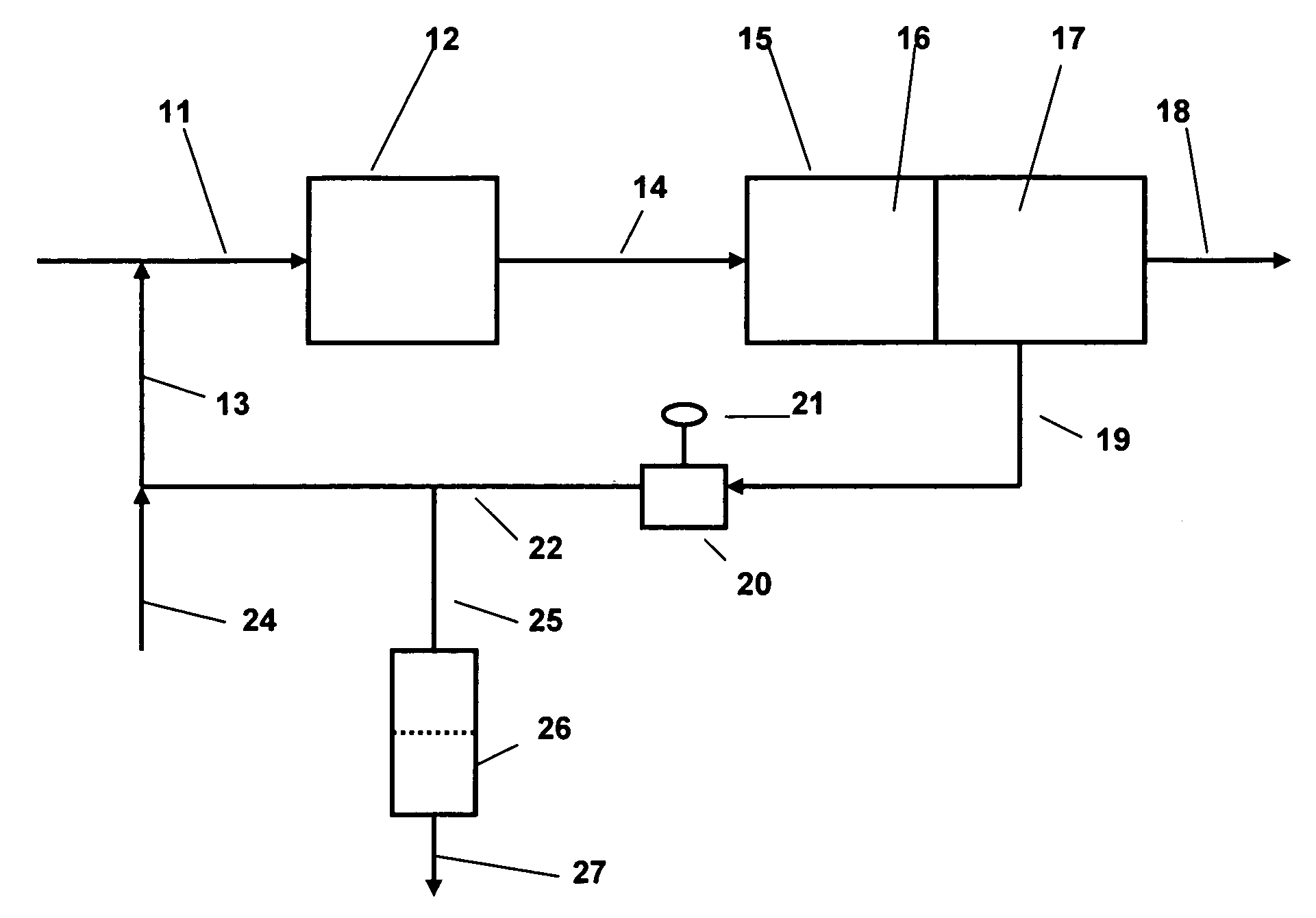
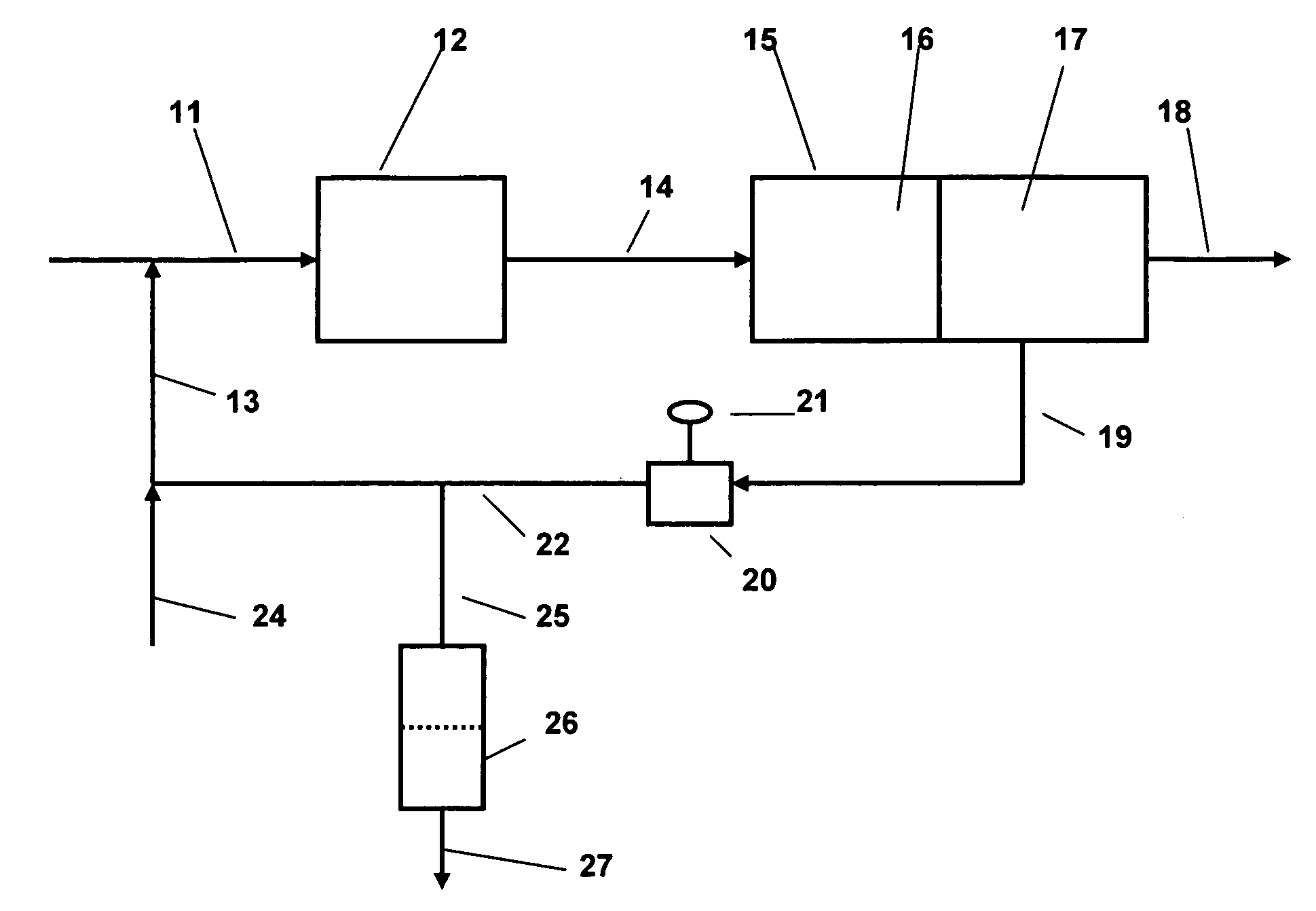
[0015]The present invention is applicable to the separation of water, either alone or mixed with other contaminants, from hydrocarbon liquids. The method is particularly applicable to the separation of water from light hydrocarbon liquids of relatively low viscosity, comparable to that of the water to be separated. The method is of particular applicability to the separation of water from refinery hydrocarbon fuels including gasoline (including heavy gasoline and light gasoline), middle distillates such as home heating oil, vaporizing oil, road diesel including all ASTM D2 diesels, kerosene type aviation fuels, as well as potentially to other liquid hydrocarbon product streams which require removal of water in order to meet product specifications or other service or commercial requirements. Normally, the amount of water which is present in these materials prior to separation will be relatively small, typically not more than about 5 volume percent, but product specifications will norm...


PUM

PropertyMeasurementUnit
freezing pointaaaaaaaaaa
temperaturesaaaaaaaaaa
freezing pointaaaaaaaaaa

Abstract

A method for the removal of dissolved water or water and ice from hydrocarbon liquids such as petroleum refinery fuels or natural gas liquids in a manner which enables the fuels to be readily treated by the coalescence / separation technique while reducing the potential for plugging filters and other equipment with ice crystals. Free water or water / ice is removed from the liquid hydrocarbons by contacting the hydrocarbon feed with a treating agent which as an affinity for water prior to subjecting the mixture to coalescence / separation. The treating agent is preferably a co-solvent for the water and the hydrocarbon such as an alcohol e.g. methanol. The treating agent and water are separated from the hydrocarbon component during the coalescence / separation and recirculated to the feed with the composition of the recycle aqueous phase being controlled to achieve the desired level of water removal to meet relevant product specifications. Consistent with the removal of the water during the coalescence / separation, the water concentration of the recycle loop containing the co-solvent / water blend gradually increases with removal of the water from the feed. This progressive increase in water level can be compensated by controlled addition of pure co-solvent to the recycle coupled with continuous or periodic dumping of excess mixture. Alternatively, the circulating mixture may be subjected to continuous or batch regeneration or disposed of in any other way which is convenient and economical.

Description

CROSS REFERENCE TO RELATED APPLICATION[0001]This application relates to and claim priority to U.S. Provisional Patent Application No. 60 / 996,602 filed on Nov. 27, 2007.FIELD OF THE INVENTION[0002]This invention relates to a method for the separation of water from hydrocarbons, especially liquid hydrocarbons such as petroleum naphthas, natural gas condensates, petroleum fuels such as gasoline, middle distillates such as road diesel fuel and kerojet, particularly under low temperature conditions. The water removed may be present as such in the hydrocarbons or mixed with other water-miscible materials or contaminants which may be removed simultaneously with the water.BACKGROUND OF THE INVENTION[0003]Significant amounts of water become mixed with hydrocarbon streams during production and processing. Petroleum refinery streams, for example, may be treated with water, steam or various aqueous solutions during processing in order to carry out the processing and to meet various quality spec...

Claims


Application Information

Patent Timeline
Patent Type & Authority Applications(United States)
IPC IPC(8): C10G33/04
CPCC10G33/04
Inventor FALKINER, ROBERT J.KAUL, BAL K.CAMPBELL, IAN D.
Owner EXXON RES & ENG CO
Why Eureka
Try Eureka