
Noise Reduction Apparatus, Systems, and Methods

a technology of noise reduction and data acquisition, applied in the field of noise reduction in data acquisition systems, can solve the problems of significant noise component, incremental effect of noise reduction methods such as signal averaging, at the cost of scan time or spatial resolution, etc., and achieve the effect of reducing noise, increasing signal-to-noise ratio, and reducing nois

Inactive Publication Date: 2009-05-28
ARJAE SPECTRAL ENTERPRISES
View PDF13 Cites 57 Cited by
  • Summary
  • Abstract
  • Description
  • Claims
  • Application Information

AI Technical Summary

Benefits of technology

[0020]In one aspect the invention relates to a method of reducing scan time of an analog signal analyzer. The method comprises receiving the broadband signal at an antenna; dividing the broadband signal into a plurality of data channels, each of the data channels spanning a frequency range; individually sampling each of the data channels into a digital components; reconstructing each of the digital components using a discrete transform to form a plurality of reconstructed data sets such that the noise of the data sets is reduced; reducing the scan time of a sample using an effective noise reduction module, the effective noise reduction module adapted to exchange signal to noise quality levels for scan time; and combining the reconstructed data sets to form a signal profile.
[0022]In one aspect the invention relates to a method of improving the effective magnetic strength of a magnetic resonance data acquisition system. The method comprises obtaining a multi-frequency signal; separating the multi-frequency signal into a plurality of frequency bands, each band of the plurality of frequency bands having a respective bandwidth; removing a noise component from each of the plurality of frequency bands to generate a plurality of noise-reduced frequency bands; and regulating the combination of a predefined number of noise-reduced frequency bands to form a combined noise-reduced frequency signal and control the effective strength of the data acquisition system.
[0024]In one aspect the invention relates to a method of reducing the number of data samples used to produce a profile. The method comprises the steps of generating a broadband signal; dividing the broadband signal into narrowband components; sampling the narrowband components at reduced sampling rates using a sampler configured based on reduced Nyquist-Shannon sampling rate limitations associated with sampling of the narrowband components rather than the broadband signal; and transforming and recombining a sampled signal from each narrowband component into the profile. In one embodiment of the method, the profile is selected from the group consisting of an image, an image profile, a signal, and a signal profile.
[0031]In one embodiment, the multi-frequency signal is generated by exciting a target portion of a target volume, the target volume comprising a plurality of target portions wherein the signal receiving element is a narrowband channel signal receiver. One narrowband multi-frequency signal can be generated for each target portion of the target volume. Further, a combination of a plurality of target portions can be excited such that the multi-frequency signal is received by a plurality of narrowband channel signal receivers. In one embodiment, the signal receiving element is a plurality of coils. At least one of the coils can be oriented in a phase encoding direction or a frequency encoding direction. In addition, at least one of the coils can be oriented in a direction other than a phase encoding direction or a frequency encoding direction. In another embodiment, the method further comprises the step of performing spectral division of the multi-frequency signal such that an increase in a signal-to-noise ratio occurs relative to not performing the spectral division. In another embodiment, the step of removing the noise component from each of the plurality of frequency bands includes identifying a plurality of magnetic gradients that encode a known spatial displacement of noise in resulting images and reducing the noise in a final image by using this known spatial displacement.
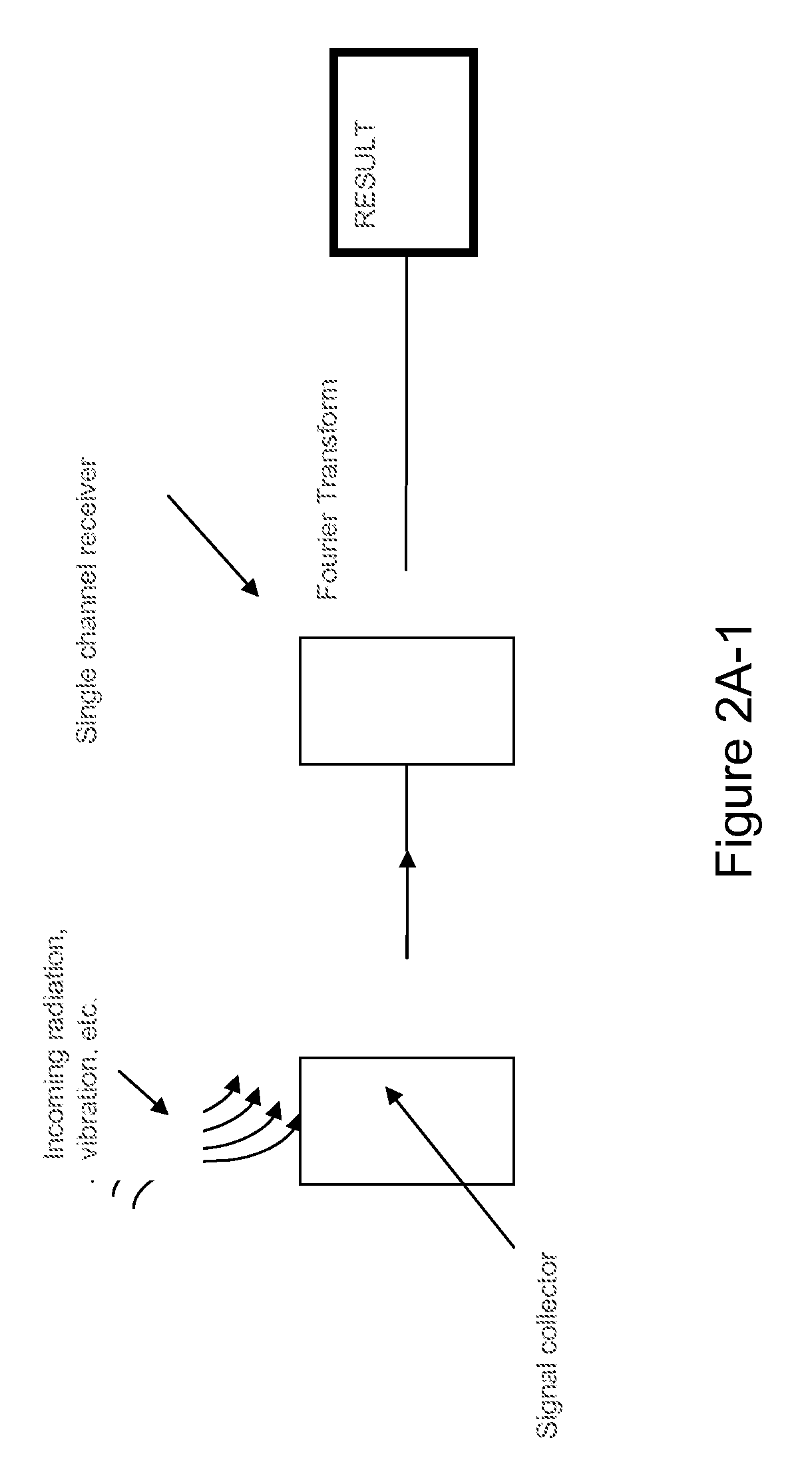
[0032]In one aspect, the invention relates to a method of reducing noise associated with a data collection event. This method includes various steps. Initially, incoming radiation / vibration is detected by signal collector as a time series signal. The time series signal is sent to a multi-channel frequency filter-bank receiver (with one or more channels). Next, the time series signal is filtered by each channel bandpass prior to A / D conversion. In addition, the recorded time series data for each channel is Fourier transformed. The noise detected during the time series is applied to each frequency comprising the channel. No noise from the other channels is introduced into each channel, thereby reducing cross frequency noise. Finally, the Fourier Transform of the recorded time series data for each channel is filtered by clipping outside the channel bandpass, and the results of each channel are summed, generating the final result. The act of clipping reduces cross-frequency noise between channels.

Problems solved by technology

Implicit in the resulting images and image / signal profiles in these technologies is a significant noise component relative to that of the desirable signal component.
Methods to reduce noise, such as signal averaging, however, typically have an incremental effect on overall SNR, at the cost of scan time or spatial resolution.

Method used


Image

  • Noise Reduction Apparatus, Systems, and Methods
  • Noise Reduction Apparatus, Systems, and Methods
  • Noise Reduction Apparatus, Systems, and Methods

Examples


first embodiment

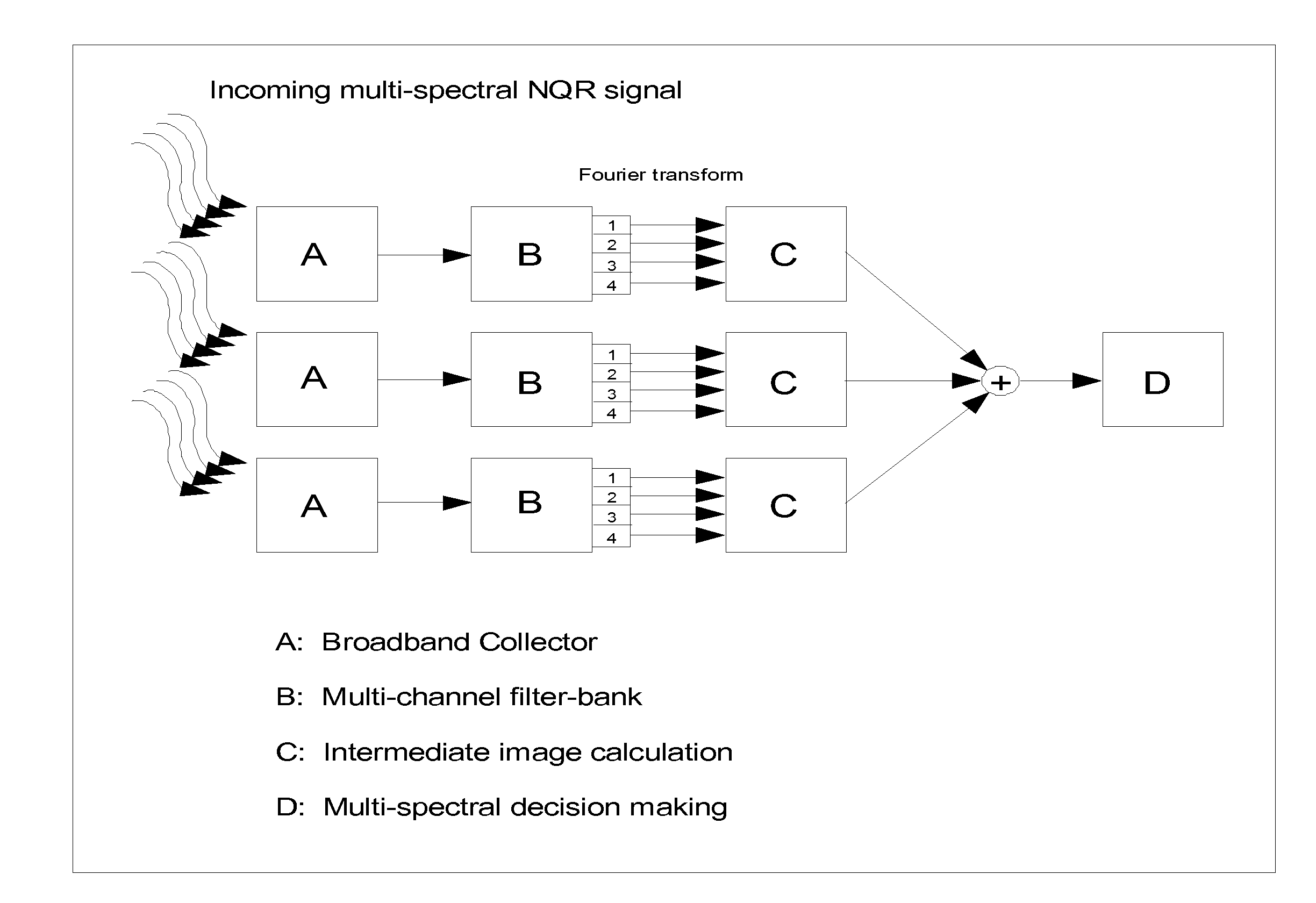
[0218]Several practical embodiments of a multi-channel CRISP NQR system are described in this section. In the first embodiment, multiple RF coils are each tuned to a distinct frequency range encompassing one or more target spectral lines. Each RF coil output is attached to a multi-channel CRISP filter-bank. This is similar to a combination of the embodiments of FIG. 2B and FIG. 2C, and is described in FIG. 7.

[0219]As shown in FIG. 7, multiple broadband RF coils receive a NQR signal. Each broadband RF coil encompasses a number of target NQR spectral lines. These lines are resolved using CRISP technology (frequency filter-bank version). In turn, calculation of intermediate images and subsequent summation creates the final image or signal profile. In one embodiment, resolved spectral peaks are then characterized according to the known distributions of the spectral lines for target substances.

second embodiment

[0220]In the second embodiment, a single broadband RF coil is tuned to a wide frequency range including many target spectral lines, and it is attached to a multi-channel CRISP filter-bank. This is similar to the CRISP embodiment described in FIG. 2B. In this case, narrowband excitation of the target in a sweeping fashion, either continuous or pulsed, is integrated with the use of a multi-channel CRISP frequency filter-bank system. In either embodiment, low noise RF coils, e.g. superconducting RF coils, low temperature RF coils may be used. Because of the breadth of the target spectral lines, it may be more optimal not to use contiguous spectral coverage with the narrowband CRISP data channels, but instead be more selective in the ranges that are covered by either the physical coils or by the frequency filter-bank.

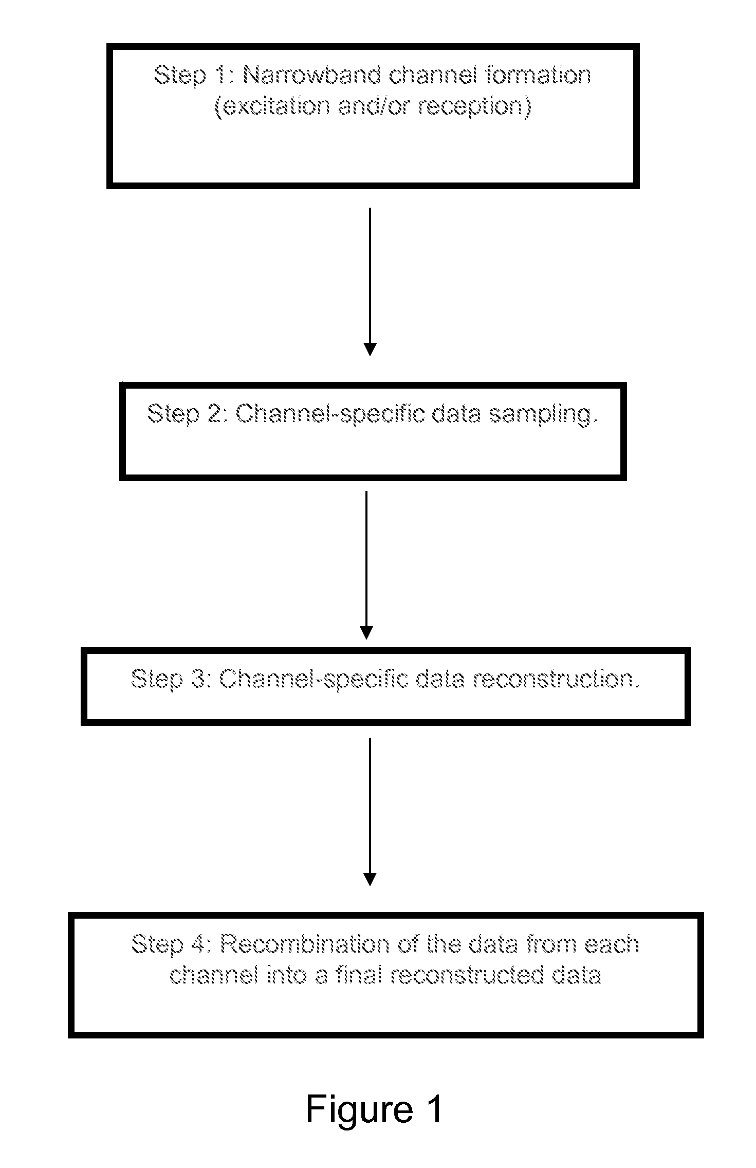
Step 2: Channel Specific Data Sampling

[0221]Data sampling is performed separately for each CRISP data channel either with a dedicated or a multiplexed A / D converter. Becaus...


PUM


Abstract

This document describes a general system for noise reduction, as well as a specific system for Magnetic Resonance Imaging (MRI) and Nuclear Quadrupole Resonance (NQR). The general system, which is called Calculated Readout by Spectral Parallelism (CRISP), involves reconstruction and recombination of frequency-limited broadband data using separate narrowband data channels to create images or signal profiles. A multi-channel CRISP system can perform this separation using (1) frequency tuned hardware, (2) a frequency filter-bank (or equivalent), or (3) a combination of implementations (1) and (2). This system significantly reduces what we call cross-frequency noise, thereby increasing signal-to-noise-ratio (SNR). A multi-channel CRISP system applicable to MRI and NQR are described.

Description

RELATED APPLICATIONS[0001]This application claims priority to U.S. Provisional Patent Application 61 / 004,427 filed on Nov. 27, 2007, U.S. Provisional Patent Application 61 / 044,228 filed on Apr. 11, 2008, the disclosures of which are herein incorporated by reference in their entirety.FIELD OF THE INVENTION[0002]The invention relates generally to the field of noise reduction in data acquisition systems. Specifically, the invention relates to methods and devices for reducing noise and other effects when data is collected.BACKGROUND OF THE INVENTION[0003]In general, there are numerous scanning technologies by which a physical object, compound, biological entity, or other sample can be investigated using targeted waves. Many modern day wave-based scanning technologies used to evaluate samples collect a multi-spectral signal using a signal collector, receive the signal (mix, filter, digitally sample), and then perform a mathematical transformation, typically a Fourier Transform (FT) or In...

Claims


Application Information

Patent Timeline
IPC IPC(8): G01R33/50G06K9/40G06K9/36
CPCG01R33/441G01R33/5608G01R33/56
Inventor HAJIAN, ARSEN R.KIM, JAE K.
Owner ARJAE SPECTRAL ENTERPRISES
Learn More