Power factor correction method for ac/dc converters and corresponding converter

a technology of ac/dc converters and power factor correction methods, which is applied in the field of power electronics, can solve problems such as the change of input impedance and input impedance, and achieve the effects of reducing the size of transformers, reducing switching currents and losses in choppers or inverters connected ahead of converters

Inactive Publication Date: 2009-06-11
TALLINN UNIVERSITY OF TECHNOLOGY
View PDF7 Cites 11 Cited by
  • Summary
  • Abstract
  • Description
  • Claims
  • Application Information

AI Technical Summary

Benefits of technology

[0021]Third advantage is a fact that instead of alternating voltage the converter with parallel and series resonance alternation could be supplied with unidirectional DC voltage pulses, which could be obtained. by means of one-transistor switch (chopper). Hereby, in transformer windings appears alternating voltage because of the capacitor recharging process in LC-circuit of the converter. In this way, a magnetic flux in the transformer is not permanently unidirectional, as it is in well-known one-transistor flyback or forward converters that enable to reduce size of the transformer.
[0022]Fourth advantage is a fact that the switching currents and losses in chopper or inverter connected ahead of the converter are reduced because of the using of the converter with parallel and series resonance alternation.

Problems solved by technology

This causes changing of the input impedance.
It also causes changing of the input impedance.

Method used


Image

  • Power factor correction method for ac/dc converters and corresponding converter
  • Power factor correction method for ac/dc converters and corresponding converter
  • Power factor correction method for ac/dc converters and corresponding converter

Examples


Embodiment Construction

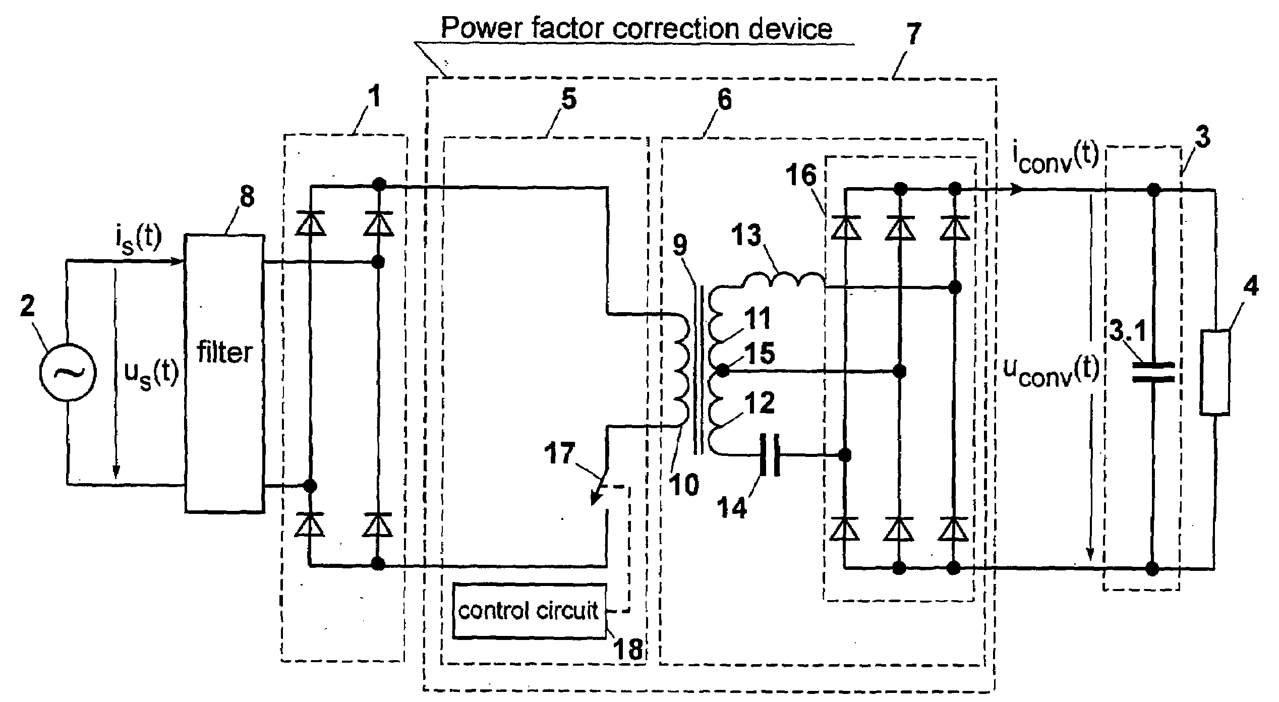
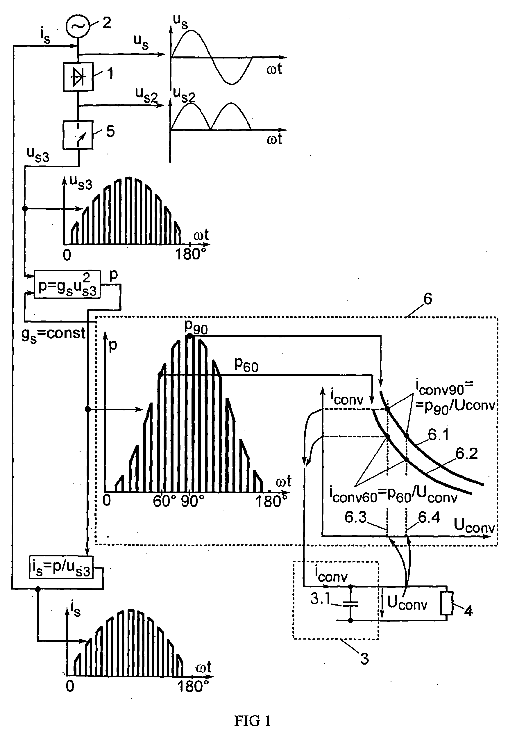
[0037]In the FIG. 1, there is shown generalized method for power factor correction in AC / DC converters. Alternating voltage us supplied from the mains 2 is delivered then to rectifier 1. After rectifying an unsmoothed half-waves of the mains voltage us2 are obtained. The rectified and smoothed voltage is delivered from smoothing filter 3 to load 4. To improve the power factor, the rectified voltage is not delivered directly to the smoothing filter 3. At first, the shape of the voltage us2 is changed by means of chopper 5. Hereby, DC voltage pulse train us3 appears wherein amplitude of the pulses is changing according to the instantaneous value of mains voltage. This pulse train is delivered to the converter circuit 6, which is able to change voltage-current relation analogously to transformer. The input admittance gs of this converter circuit is constant and it consumes instantaneous power p from the mains, which could be defined by multiplication of the input admittance gs and volt...


PUM


Abstract

An indirect and passive method for AC/DC( converter power factor correction is disclosed. The correction is achieved by stabilizing the input impedance of the converter with keeping the inversely proportional dependence between the current iconv(t) and voltage uconv(t) of the output smoothing filter (3). The necessary dependence is achieved by natural characteristics of circuit with passive components. An uncontrolled converter (6) with alternation of parallel and series resonance is used as such circuit. To increase the operating frequency of this converter, a chopper or an inverter is used. The resonant converter decreases the commutation current of the switches. Output voltage is easy to control by pulse width modulation of chopper or inverter. Passive power factor correction results in the total harmonic distortion of main current THDi=10 to 40 per cent. All currents of the converter are limited naturally in all operating modes.

Description

TECHNICAL FIELD[0001]The present invention relates to the power electronics and can be used in AC / DC converters to reduce distortion of AC side current and thus, to improve the power factor of the converters. The invention is particularly useful in converters with frequent short circuit operating, e.g., in power supplies for electric arcs.BACKGROUND ART[0002]There are known passive power factor correction methods that use a network frequency LC resonance circuits operating as a higher frequency harmonic filter. For instance, a higher harmonics filter is connected in series with a bridge rectifier on its AC side (A. R. Prasad, P. D. Ziogas, S. Manias. Passive input current waveshaping method for three-phase diode rectifiers. IEE Proceedings-B, Vol. 139, No. 6, November 1992, pp. 512-520). There is also known a converter with parallel and series resonance alternation (K. Janson, J. Järvik. AC-DC Converter with Parametric Reactive Power Compensation. IEEE Trans. Power Electron, Vol. 46...

Claims


Application Information

Patent Timeline
Patent Type & Authority Applications(United States)
IPC IPC(8): G05F1/70H02M1/00H02M1/42
CPCH02M1/4241Y02B70/126H02M1/4258Y02B70/10
Inventor JANSON, KUNOJARVIK, JAANSHKLOVSKI, JEVGENI
Owner TALLINN UNIVERSITY OF TECHNOLOGY
Why Eureka
Try Eureka