Nano particle reinforced polymer element for stator and rotor assembly

Inactive Publication Date: 2009-06-18
HALLIBURTON ENERGY SERVICES INC
View PDF87 Cites 147 Cited by
  • Summary
  • Abstract
  • Description
  • Claims
  • Application Information

AI Technical Summary

Benefits of technology

[0028]The polymer host material and the nano structures may interact via interfacial interactions, such as co-polymerization, crystallization, van der Waals interactions, covalent bonds, ionic bonds, and cross-linking interactions. The interfacial interactions may be improved by chemical functionalization of the nano particles.
[0029]Incorporation of nano particles in the polymer improves the particle reinforced polymer matrix by reducing processing viscosity, improving impact strength, improving stress relaxation resistance, improving compression set properties, increasing tear strength, increasing resistance to thermal and hysteresis, reducing heat buildup failure, increasing thermal conductivity, reducing creep, improving resilience and abrasion resistance, and improving resistance to chemical degradation of the polymer.
[0030]Nano

Problems solved by technology

Slip results in speed and power reduction of a power section until, at some point, the power section stalls, allowing substantially all fluid to bypass the interface between the rotor and the stator with no resultant rotation produced by the power section.
Failure of the polymer element of a power section of a positive displacement fluid motor or a progressive cavity pump typically occurs due to high mechanical loading, polymer fatigue, incompatibility of the fluid and polymer, or high temperature effects on the polymer element.
Failure may be associated with a reduction in the performance of the polymer element or with catastrophic failure.
Mechanical failure of the polymer element occurs when the polymer is subject to conditions that exceed the critical strain limit or when the polymer is subject to excessive cyclic loading.
Excessive polymer temperatures generally result from high downhole temperature, hysteresis heat buildup caused by repeated flexing of the polymer by the lobes rotor and pressuri

Method used


Image

  • Nano particle reinforced polymer element for stator and rotor assembly
  • Nano particle reinforced polymer element for stator and rotor assembly
  • Nano particle reinforced polymer element for stator and rotor assembly

Examples


Example

[0050]In the following description, numerous details are set forth to provide an understanding of the present invention. It should be understood by those of ordinary skill in the art that the present invention may be practiced without these details and that numerous variations or modifications from the described embodiments may be possible. The specific embodiments discussed herein are merely illustrative of specific ways to make and use the invention and do not delimit the scope of the present invention.

[0051]The present invention generally relates to a system and method of manufacture for an improved polymer element of a stator and rotor assembly. The system and method are useful, for example, with a variety of applications related to a power section of a positive displacement fluid motor or a progressive cavity pump or a fluid pulse generating device; for example, Halliburton's Pulsonix Deep Wave technology.

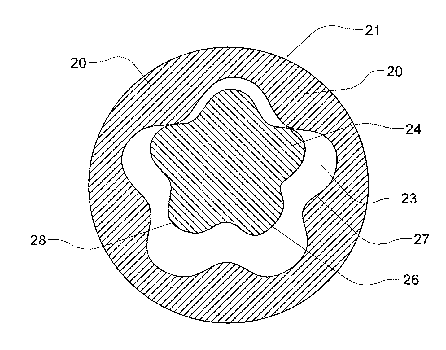
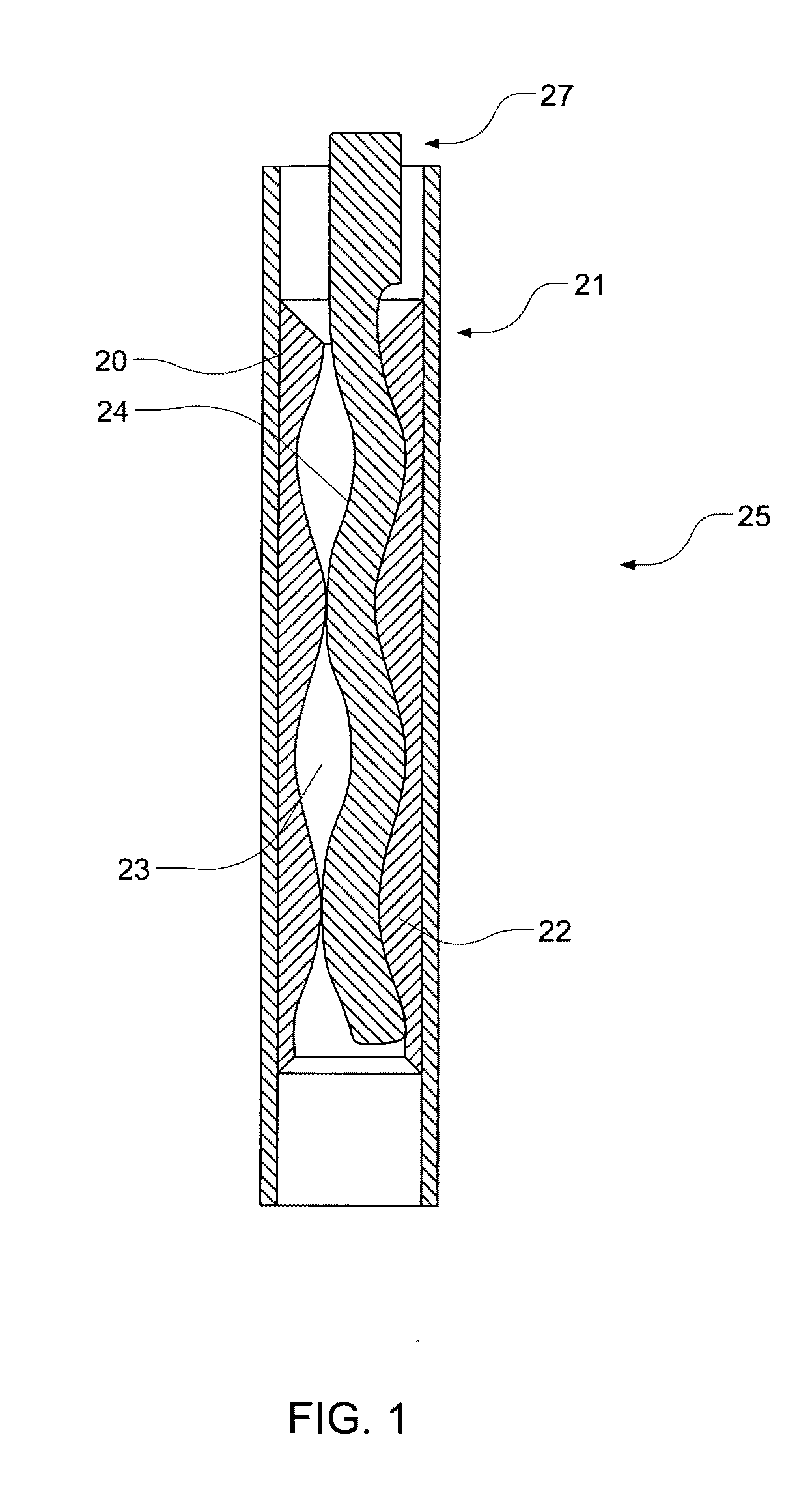
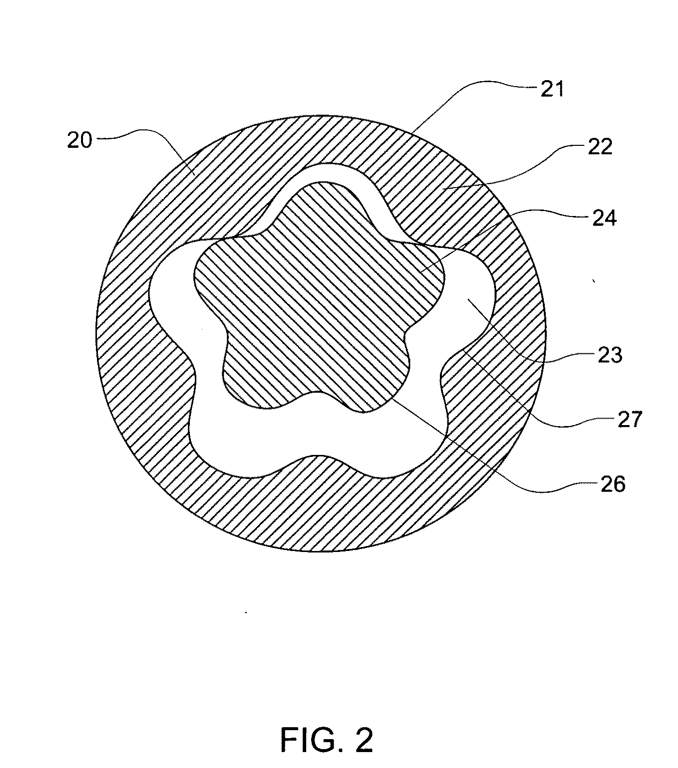
[0052]Referring generally to FIG. 1, a system 25 is illustrated according...


PUM

PropertyMeasurementUnit
Nanoscale particle sizeaaaaaaaaaa

Abstract

A nano particle reinforced polymer element of a stator and rotor assembly for a power section of a positive displacement fluid motor or a progressive cavity pump. Nano-sized particles are blended with an uncured polymer to improve the physical and chemical properties of the polymer. The use of nano-sized particles reduces the quantity of reinforcement material required to manufacture the polymer for the stator and rotor assembly and lowers the viscosity of the uncured polymer to improve manufacturing characteristics. The use of chemically functionalized nano particles improves the chemical and physical characteristics of the polymer.

Description

FIELD OF THE INVENTION[0001]This invention relates, in general, to a polymer element of a stator and rotor assembly for power sections of positive displacement downhole fluid motors and progressive cavity pumps and, in particular, to an improved polymer element of a stator or rotor element comprised of a nano particle reinforced polymer internally disposed in a stator lining or disposed as a uniform compliant layer along a rotor surface.BACKGROUND OF THE INVENTION[0002]Without limiting the scope of the present invention, its background will be described with reference to stator and rotor assemblies of power sections of positive displacement fluid motors and progressive cavity pumps, as examples.[0003]A typical power section of a positive displacement fluid motor comprises a helical-shaped steel rotor that turns rotatably about the centerline of a polymer-lined stator and rotor assembly. A typical stator is a steel tube, lined with a bonded polymer with a helical-shaped inner cavity....

Claims


Application Information

Patent Timeline
IPC IPC(8): E21B4/02F01C1/107F04C18/107F04C15/00F04C2/107
CPCC08K5/549C08K7/24E21B4/02F04C15/0015F01C1/107F04C2/1071E21B43/128C08K3/041C08L101/00C08K9/00
Inventor SLAY, JEREMY BUCRAY, THOMAS WAYNE
Owner HALLIBURTON ENERGY SERVICES INC
Why Eureka
Try Eureka