
Method for manufacturing semiconductor device

a manufacturing method and semiconductor technology, applied in the field of semiconductor device manufacturing, can solve the problems of increasing the number of processes, defective patterns, and difficulty in forming fine patterns having cd below the short wavelength, and achieve the effect of improving yield and reliability of semiconductor devices

Inactive Publication Date: 2009-07-02
SK HYNIX INC
View PDF3 Cites 9 Cited by
  • Summary
  • Abstract
  • Description
  • Claims
  • Application Information

AI Technical Summary

Benefits of technology

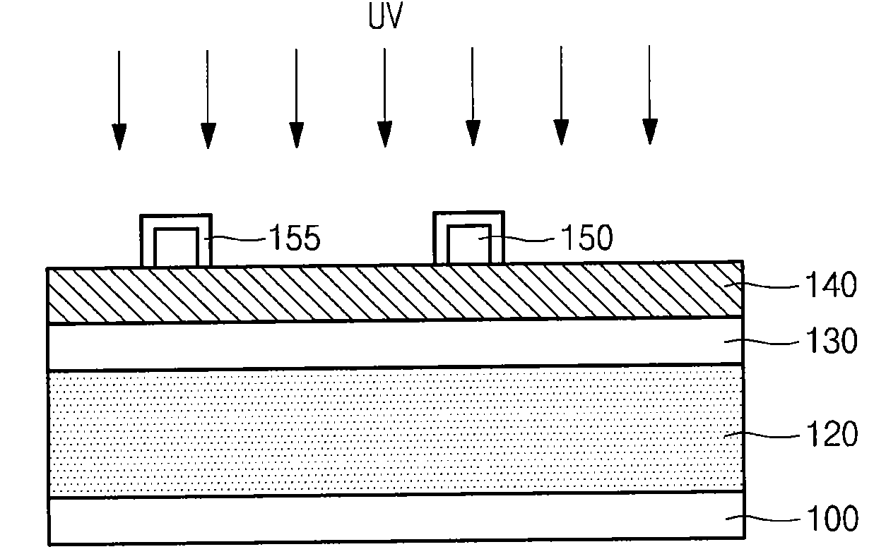
[0023]Various embodiment of the present invention relate to a method for manufacturing a semiconductor device that comprises: irradiating using ultraviolet light after forming a first photoresist pattern; and forming a crosslink layer that serves as a barrier film over the first photoresist pattern, thereby improving yield and reliability of the semiconductor device.

Problems solved by technology

As a result, it is difficult to form a fine pattern having a CD below the short wavelength.
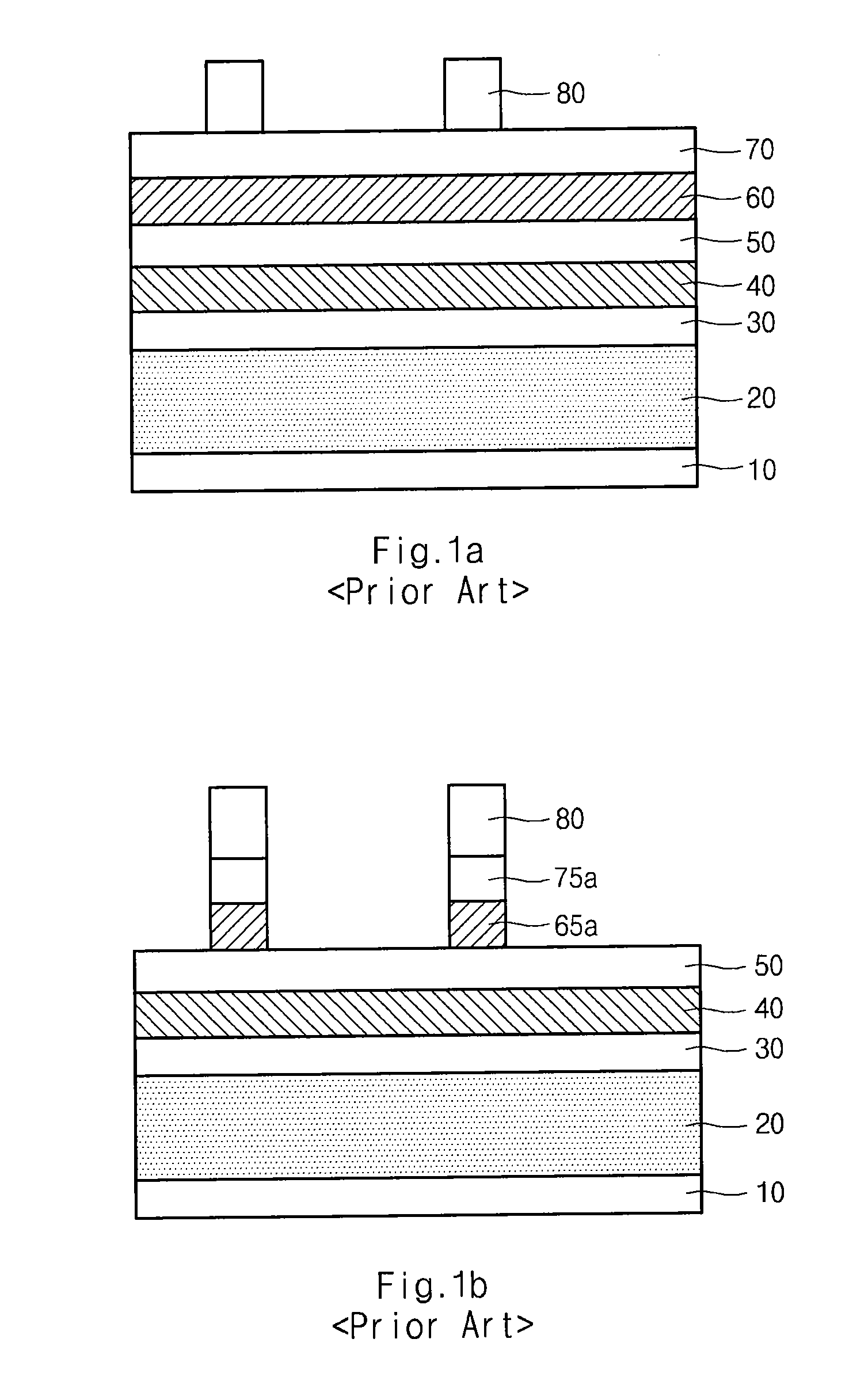
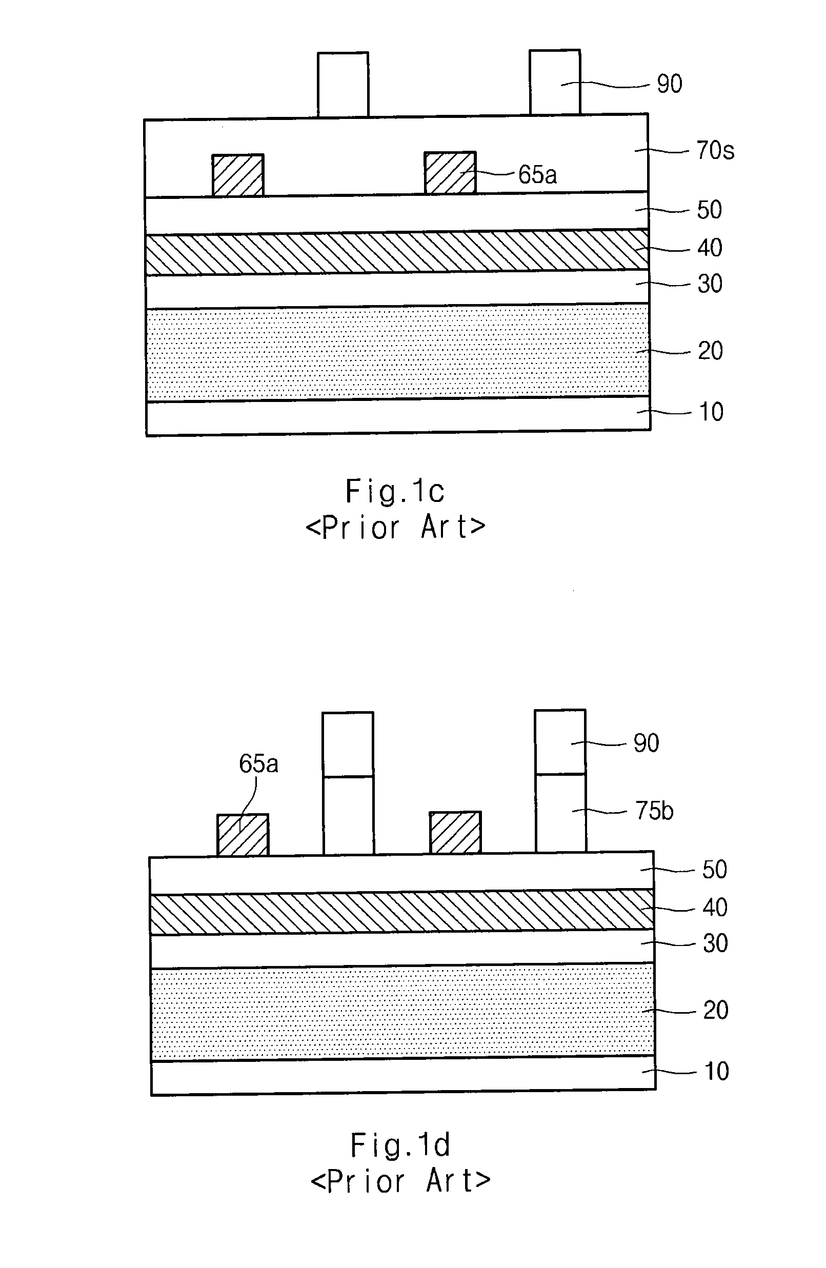
If the first photoresist pattern is combined with the second photoresist pattern, a defective pattern is created.
As a result, the number of processes is increased and a defect ratio is increased, thereby degrading yield and reliability of the semiconductor device.

Method used


Image

  • Method for manufacturing semiconductor device
  • Method for manufacturing semiconductor device
  • Method for manufacturing semiconductor device

Examples


Embodiment Construction

[0030]FIGS. 2a to 2h are diagrams illustrating a method for manufacturing a semiconductor device according to an embodiment of the present invention.

[0031]Referring to FIG. 2a, an underlying layer (not shown) is formed over a semiconductor substrate 100. A hard mask layer 120, an etching barrier film 130 and an anti-reflective film 140 are sequentially formed over the underlying layer. The underlying layer includes one selected from the group consisting of a nitride film, an oxide film, BPSG, PSG, USG, PE-TEOS, polysilicon, tungsten, tungsten silicide, cobalt, cobalt silicide, titanium silicide, aluminum and combinations thereof, to have a thickness ranging from 200 to 5000 Å.

[0032]The hard mask layer 120 includes one selected from the group consisting of an amorphous carbon (a-C) layer, a polysilicon layer, a SiON film, an oxide film and combinations thereof. The etching barrier film 130 includes a silicon oxide nitride (SiON) film. The anti-reflective film 140 has a single-layered...


PUM


Abstract

A method for manufacturing a semiconductor device comprises: forming a first photoresist pattern in a double patterning technology (DPT) for overcoming a resolution limit of an exposer; and forming a second photoresist pattern. The method further comprises forming a hard mask film and an anti-reflective film to prevent an intermixing phenomenon generated when the second photoresist pattern is formed. As a result, yield and reliability of the process can be improved.

Description

CROSS-REFERENCE TO RELATED APPLICATION[0001]This application is based upon and claims the benefit of priority to Korean Patent Application No. 10-2007-0141511, filed on Dec. 31, 2007, the entire contents of which are incorporated herein by reference.BACKGROUND OF THE INVENTION[0002]The present invention relates to a method for manufacturing a semiconductor device, and more particularly, to a manufacturing method for a double patterning technology (DPT) which reduces the number of required layers and steps by using a crosslinked layer. As a result, yield and reliability of the process can be improved.[0003]Due to the miniaturization and increased integration of semiconductor devices, the whole chip area is increased in proportion to an increase in memory capacity, but an area for a cell region pattern of a semiconductor device is reduced.[0004]In order to secure a desired memory capacity, a large number of patterns should be formed in a limited cell region area. A critical dimension ...

Claims


Application Information

Patent Timeline
IPC IPC(8): G03F7/20H01L21/306
CPCG03F7/0035H01L21/0337G03F7/40G03F7/70466H01L21/0273H01L21/31144
Inventor LIM, HEE YOUL
Owner SK HYNIX INC
Learn More