Housing for an Implantable Medical Device

Active Publication Date: 2009-07-02
CYBERONICS INC
View PDF109 Cites 94 Cited by
  • Summary
  • Abstract
  • Description
  • Claims
  • Application Information

AI Technical Summary

Benefits of technology

[0017]Described herein is a hermetically sealed implantable medical device housing having a construction permitting for efficient magnetic coupling and RF telemetry via a non-metal housing free path from the implantable device electronics to the remote c

Problems solved by technology

Additionally, many implantable devices require such a significant amount of power that it is necessary to utilize transcutaneous energy transmission (TET) from an extracorporeal source to an implanted receiver which is connected to a rechargeable battery.
However, implant enclosures made of conductive metal present difficulties with respect to both transcutaneous energy transmission and telemetry.
With respect to RF telemetry from the implanted device to a receiver external to the patient, the metal case acts as a Faraday cage and tends to limit the rate of information transfer between the implanted device and the external system due to circulating eddy currents that absorb energy from the magnetic field and produce a magnetic field that opposes the incident magnetic field.
The carrier frequency for telemetry is limited by the amount of eddy current attenuation that the system can tolerate.
Raising the operating frequency, however, increases the eddy current losses, so that the overall induction system efficiency is severely reduced.
Additionally, such induced eddy currents create unwanted heat within the implantable enclosure.
This approach has, however, primarily been li

Method used


Image

  • Housing for an Implantable Medical Device
  • Housing for an Implantable Medical Device
  • Housing for an Implantable Medical Device

Examples


Embodiment Construction

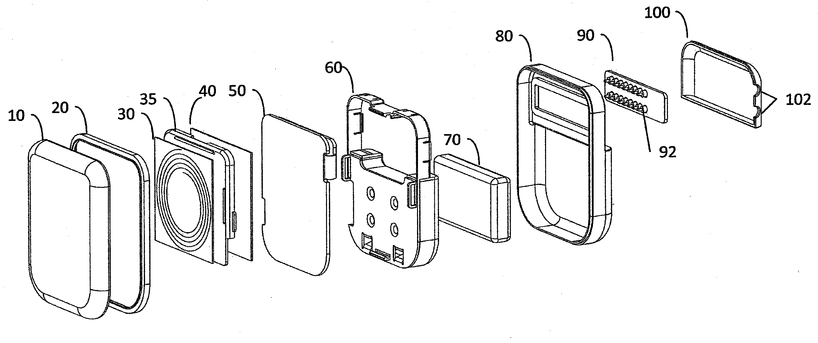
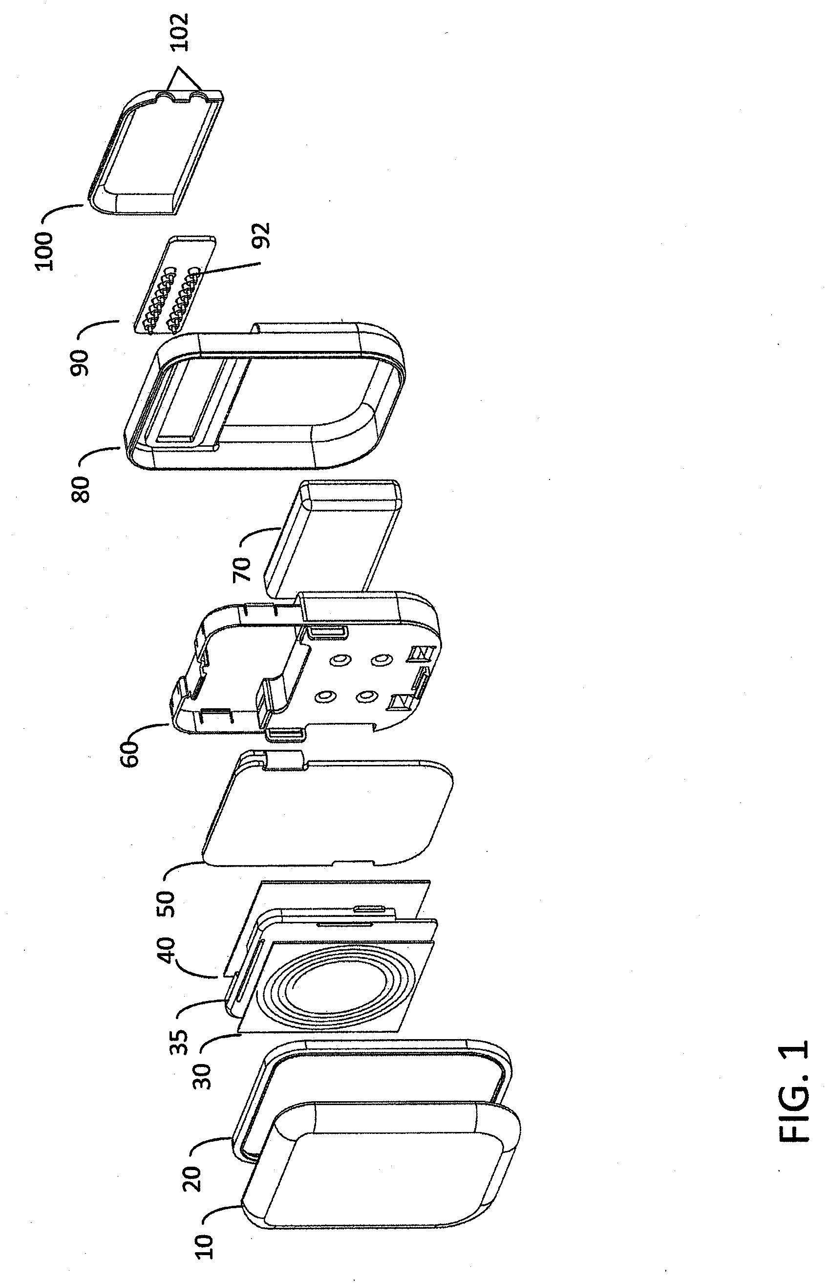
[0029]FIG. 1 is an exploded perspective view of a hermetically sealed implantable medical device according to one embodiment of the invention. The medical device housing includes ceramic housing component 10 which is made of ceramic material such as, for example without limitation, zirconium oxide, yttrium stabilized zirconium oxide, aluminum oxide, boron nitride, or other suitable material. When implanted, ceramic component 10 is disposed proximate the patient's skin, i.e., it is disposed between the portion of the patient's skin where an extracorporeal charging and / or telecommunication device will be positioned and the implanted trans-housing magnetic flux component(s), such as an implanted telemetry coil or battery charger coil (see e.g., FIG. 5). The ceramic proximal housing component 10 therefore allows magnetic flux associated with inductive charging and / or radio frequency / inductive telemetry to efficiently pass through the hermetically sealed enclosure proximal face without i...


PUM


Abstract

An implantable medical device having a concave ceramic housing component; a concave metal housing component attached to the ceramic housing component to form a hermetically sealed enclosure; and an electronic trans-housing magnetic flux component disposed within the enclosure. Another aspect of the invention provides an implantable medical device having a ceramic housing component; a metal housing component; a circumferential sealing member attached to a periphery of the ceramic housing component and to a periphery of the metal housing component to form a hermetically sealed enclosure; and an electronic trans-housing magnetic flux component disposed within the enclosure. Still another aspect of the invention provides an implantable medical device with a first metal housing component; a second metal housing component, the second metal housing component forming an opening; a ceramic housing component disposed in the opening, the first metal housing component, the second metal housing component and the ceramic housing component cooperating to form a hermetically sealed enclosure; and an electronic trans-housing magnetic flux component disposed within the enclosure.

Description

CROSS REFERENCE TO RELATED APPLICATIONS[0001]This application claims the benefit of U.S. Provisional Application No. 61 / 017,504, filed Dec. 28, 2007, which is incorporated in its entirety by reference as if fully set forth herein.INCORPORATION BY REFERENCE[0002]All publications and patent applications mentioned in this specification are herein incorporated by reference to the same extent as if each individual publication or patent application was specifically and individually indicated to be incorporated by reference.BACKGROUND OF THE INVENTION[0003]The present invention relates to an electronic medical device for implanting into a living body, and more particularly to the structure and method of manufacture of the device's outer housing for the purposes of enhancing the device's transcutaneous electromagnetic coupling to extracorporeal systems for the transfer of energy and / or information via telemetry. Such implantable devices include, without limitation, pacemakers; defibrillator...

Claims


Application Information

Patent Timeline
IPC IPC(8): A61N1/05A61N1/08
CPCA61N1/3787A61N1/375A61N1/37223A61N1/3758
Inventor BROWN, DAVIDGENAU, CHRISTOPHERLEYDE, KENT W.GAW, SHANSTEWART, JEFFREY
Owner CYBERONICS INC
Why Eureka
Try Eureka