
Method of fabricating a shallow trench isolation structure including forming a second liner covering the corner of the trench and first liner.

a technology of isolation structure and shallow trench, applied in the direction of semiconductor devices, semiconductor/solid-state device details, electrical devices, etc., can solve the problems of short current between devices, divoting or inducing more serious damage, etc., and achieve the effect of avoiding leakage curren

Inactive Publication Date: 2009-07-23
UNITED MICROELECTRONICS CORP
View PDF26 Cites 49 Cited by
  • Summary
  • Abstract
  • Description
  • Claims
  • Application Information

AI Technical Summary

Benefits of technology

[0006]The present invention provides a method of fabricating a STI structure to prevent the divot from forming near the corner of the STI structure and to avoid the leakage current of the device.
[0007]The present invention also provides a STI structure with effective isolation to prevent the short current from occurring between devices.
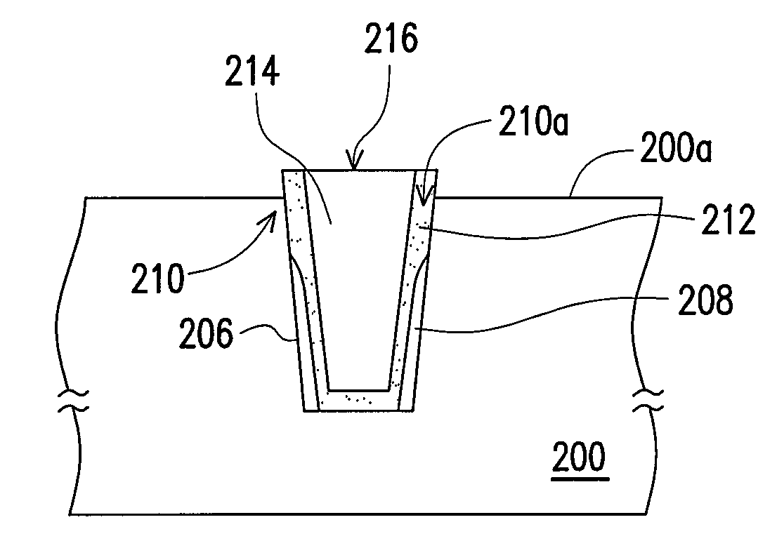
[0028]The second liner formed at the corners of the trench according to the present invention can protect the corners of the shallow trench isolation structure from being damaged by the etchant or cleaning solution, and thus avoid the generation of the divot in the corners of the STI structure. Therefore, in accordance to the present invention, the isolation capability is effectively enhanced and the leakage current is obviated. Further, based on the present invention, the short current is prevented from occurring between devices and the reliability and the yield of the device are improved.

Problems solved by technology

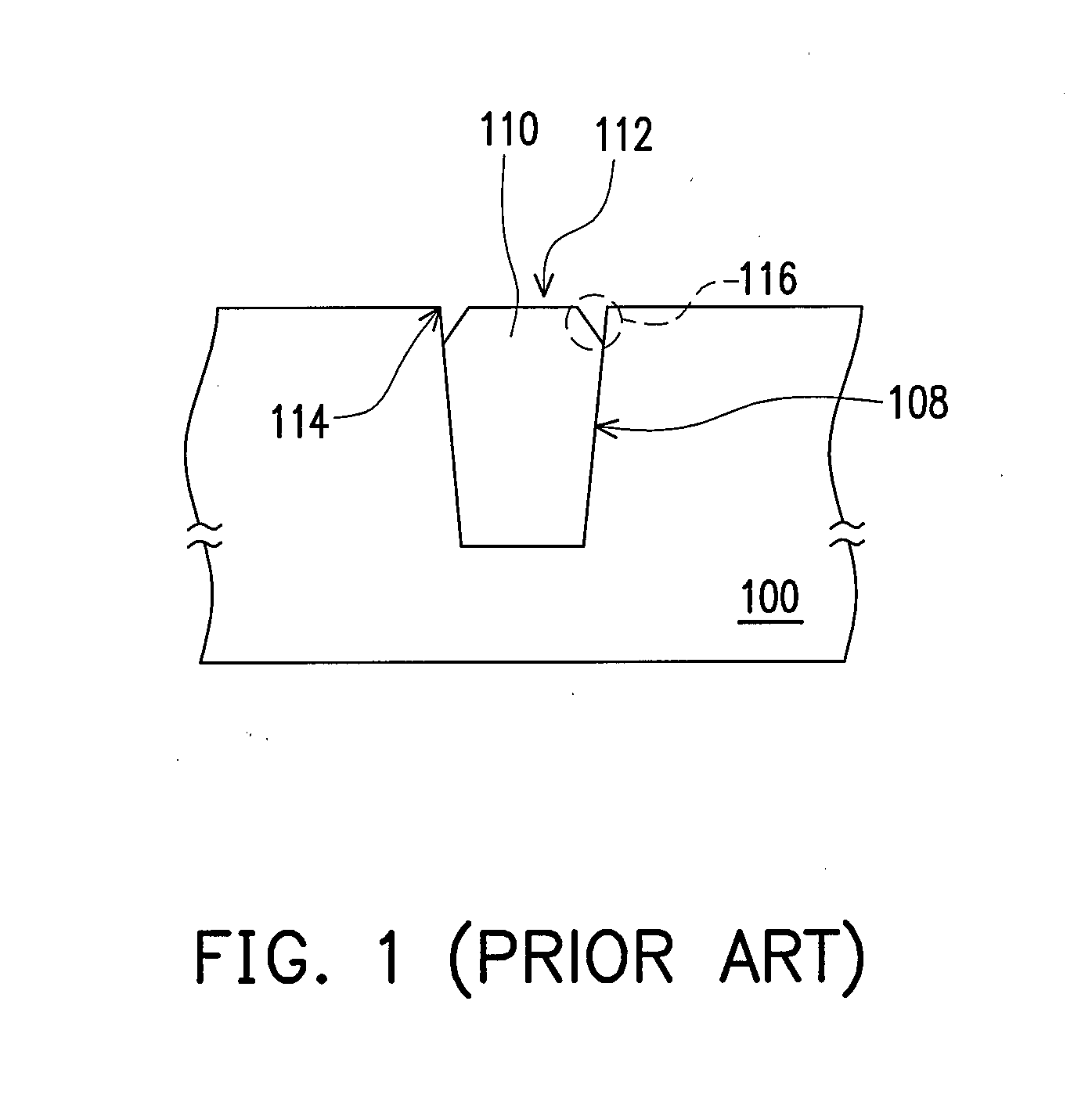
In addition, after forming the shallow trench isolation structure 112, the etchant of hydrofluoric acid and phosphoric acid used for the subsequent cleaning process steps also generate divots or induce more serious damages.
Thus, the shallow trench isolation structure formed from the conventional method generates the leakage current easily; hence, a short current between devices is resulted.

Method used


Image

  • Method of fabricating a shallow trench isolation structure including forming a second liner covering the corner of the trench and first liner.
  • Method of fabricating a shallow trench isolation structure including forming a second liner covering the corner of the trench and first liner.
  • Method of fabricating a shallow trench isolation structure including forming a second liner covering the corner of the trench and first liner.

Examples


Embodiment Construction

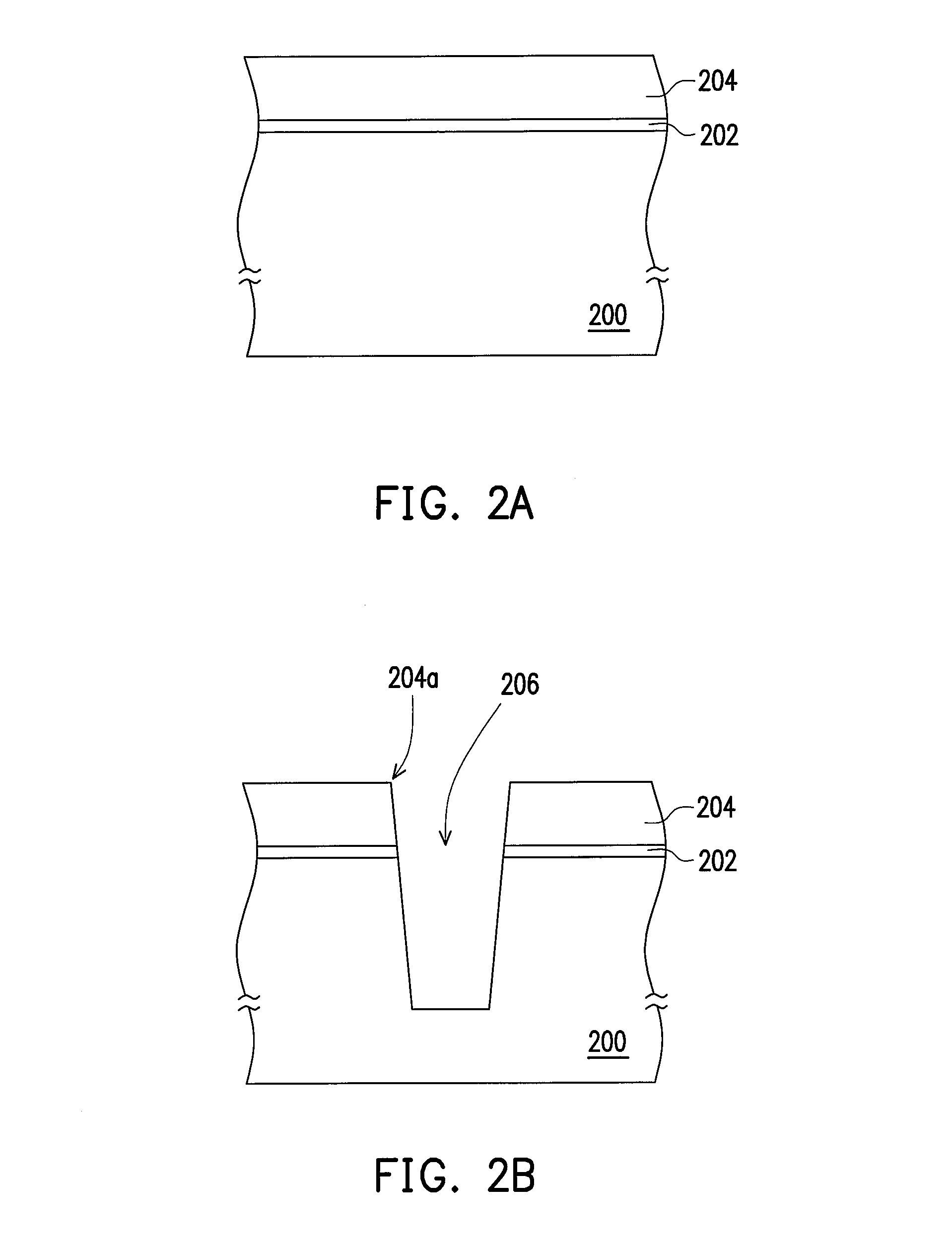
[0032]FIGS. 2A-2E are schematic cross-sectional views illustrating a process flow of fabricating a shallow trench isolation structure according to an embodiment of this invention.

[0033]Referring first to FIG. 2A, a pad oxide layer 202 and a mask layer 204 are sequentially formed on a substrate 200. The substrate 200 may be P-doped silicon, N-doped silicon, epitaxial silicon (epi-Si), gallium arsenide (GaAs), indium phosphide (InP) or germanium silicon (GeSi). The material of the pad oxide layer 202 is silicon oxide, for example. The method of forming the pad oxide layer 202 is, for example, a thermal oxidation process or a chemical vapor deposition (CVD) process. The material of the mask layer 204 is silicon nitride, for example. The method of forming the mask layer 204 is, for example, a CVD process.

[0034]Referring to FIG. 2B, the pad oxide layer 202 and the mask layer 204 are patterned and then a trench 206 is formed in the substrate 200. In one embodiment, a photolithography-and-...


PUM


Abstract

A method of fabricating a shallow trench isolation structure is provided. First, a pad oxide layer and a mask layer are formed sequentially on a substrate. Then, the mask layer and the pad oxide layer are patterned and the substrate is etched to form a trench. After that, a first liner is formed in the trench. Thereafter, a portion of the first liner is removed to expose corners of the trench. Then, a second liner is formed over the substrate to cover the corners of the trench and the first liner. The material of the second liner is different from that of the first liner. An insulation layer is further formed over the substrate to fill up the trench. The insulation layer, the second liner, the mask layer and the pad oxide layer outside the trench are eventually removed.

Description

BACKGROUND OF THE INVENTION[0001]1. Field of Invention[0002]The present invention relates to an isolation structure and a method of fabricating the same. More particularly, the present invention relates to a shallow trench isolation (STI) structure and a method of fabricating the same.[0003]2. Description of Related Art[0004]Device dimensions are getting smaller and entering a field of deep submicron or less in accordance with the development of semiconductor technology. To prevent a short current from occurring between adjacent devices, an isolation structure between devices becomes very important. A frequently used method in forming an isolation structure is the shallow trench isolation (STI) process. The isolation region formed from the above technique has the advantage of scalable dimension, and a bird's beak encroachment caused by a traditional technique of local oxidation of silicon (LOCOS) can be avoided. Therefore, the shallow trench isolation structure is a better technique...

Claims


Application Information

Patent Timeline
IPC IPC(8): H01L21/762H01L23/58
CPCH01L21/76232H01L23/58H01L2924/0002H01L2924/00
Inventor CHEN, CHUNG-CHIH
Owner UNITED MICROELECTRONICS CORP
Learn More