Method for controlling catalyst and filter temperatures in regeneration of a catalytic diesel particulate filter

a technology of catalyst and filter temperature, which is applied in the field of regenerating a catalytic diesel particulate filter, can solve the problems of affecting the efficiency of diesel engines

Inactive Publication Date: 2009-07-30
DELPHI TECH INC
View PDF5 Cites 26 Cited by
  • Summary
  • Abstract
  • Description
  • Claims
  • Application Information

AI Technical Summary

Benefits of technology

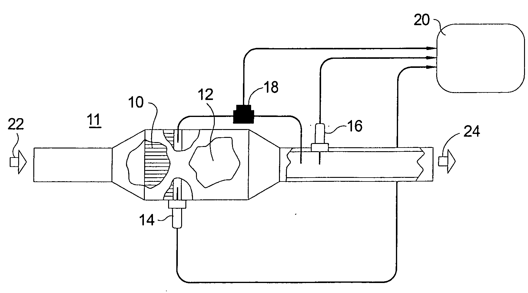
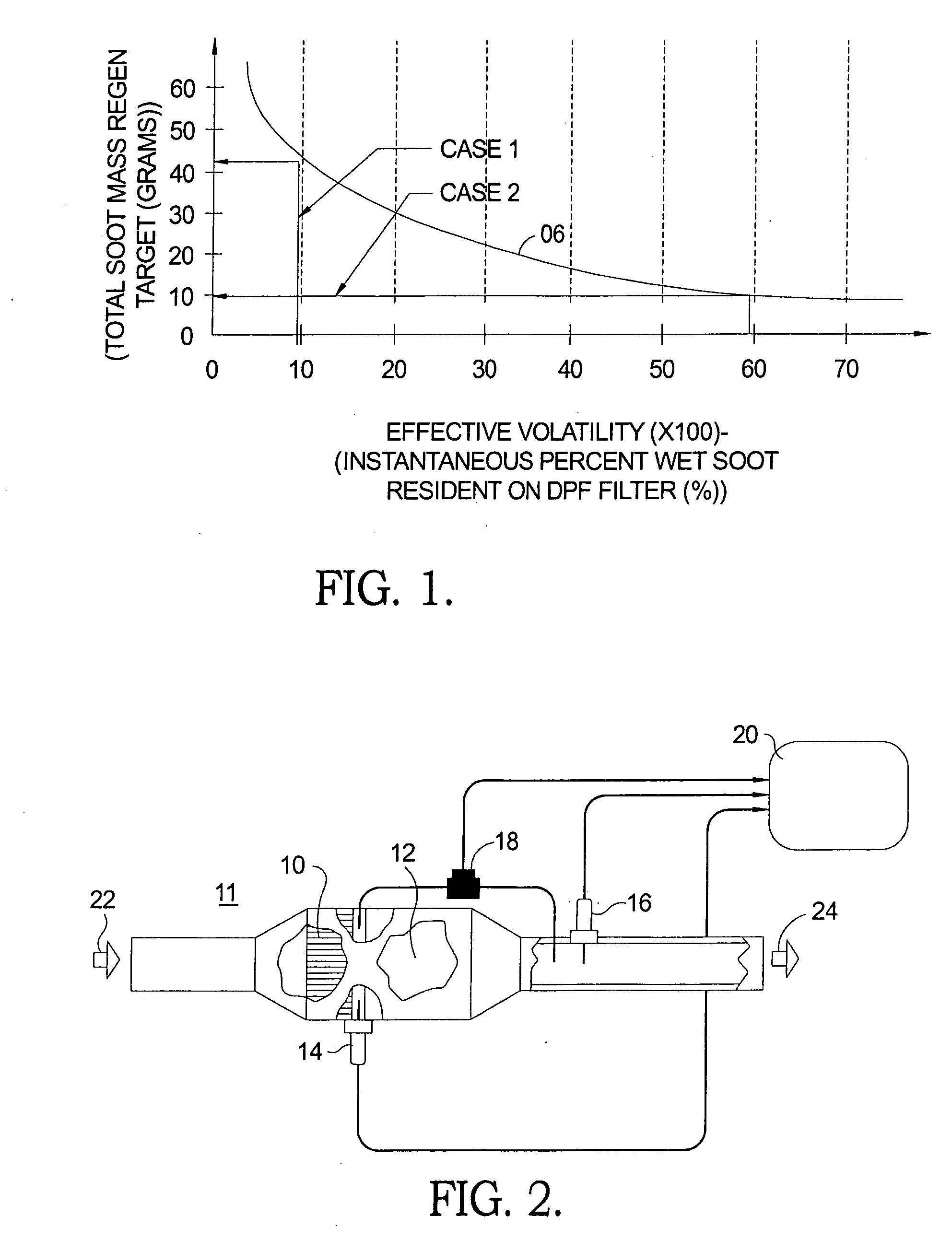
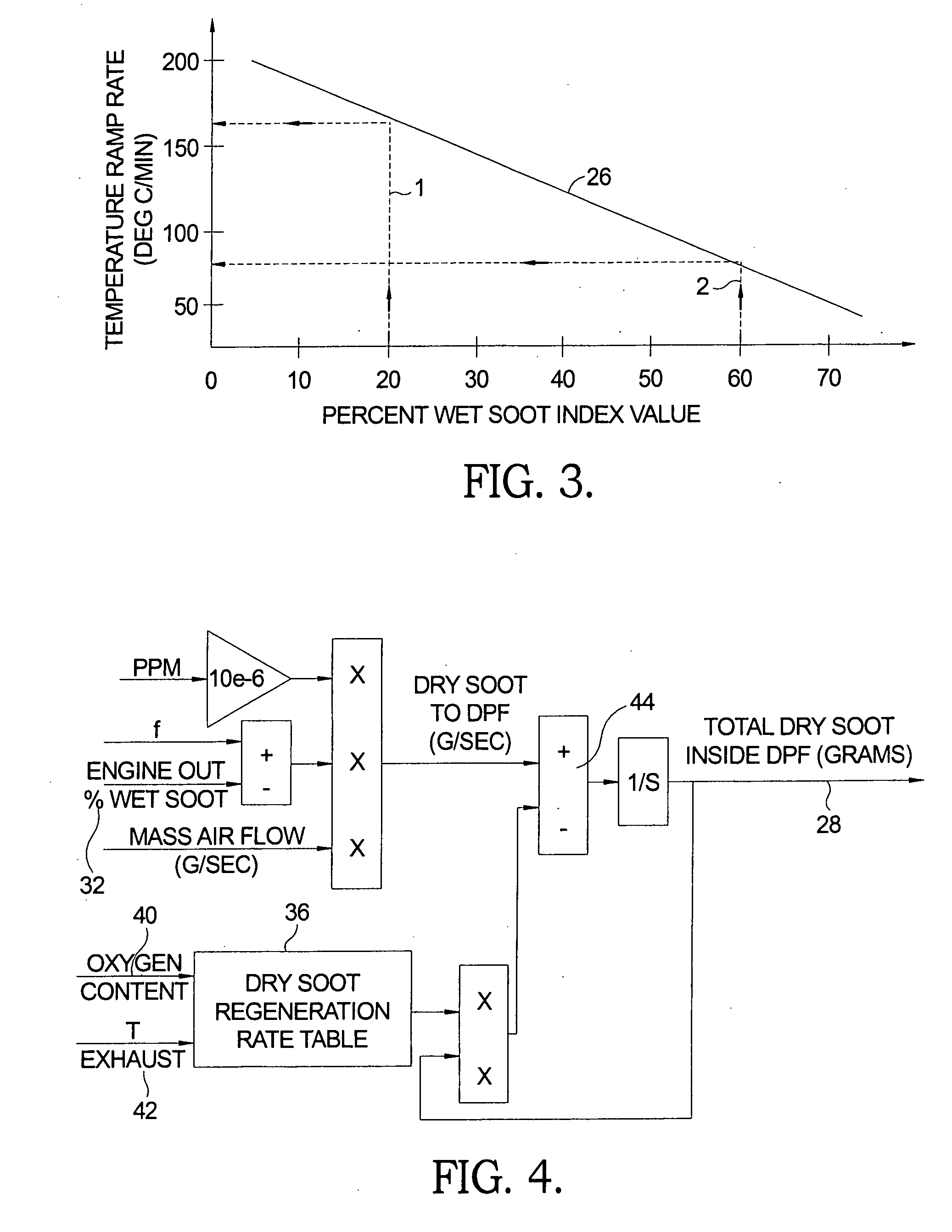
[0013]Additionally, this method allows for scaling of the soot mass threshold value based upon the wet soot accumulation in the filter and the real time accumulation rate. As such, a control method is employed to adjust the soot load trigger value as an Equivalent Soot Mass that is an indicator of the volatility / combustibility of the soot accumulation and can be utilized in a process that protects the CDPF monolith. The method provides an allowable temperature ramp rate of regeneration during a warm-up phase, total regeneration time required, and an oxygen control scheme to moderate or extinguish a runaway regeneration event.

Problems solved by technology

While diesel engines are known to be more economical to run than spark-ignited engines, diesel engines inherently suffer disadvantages in the area of emissions.
However, catalytic diesel particulate filters (CDPF) progressively load up with accumulated soot and therefore must be repeatedly regenerated by catalytically oxidizing the trapped particulates, typically on a fixed schedule and by fuel enrichment of the exhaust stream entering the CDPF.
Typically, prior art regeneration systems are temperature based with the primary protection strategy being limitation of the quantity of soot allowed to accumulate.
As shown below, this serves to under-utilize the filter capacity and results in a penalty in fuel economy.
A currently challenging durability issue in the CDPF art is cracking or melting of a CDPF substrate due to large temperature excursions within the bed of the filter during regeneration.
This combination of events (rapid combustion and low cooling) can result in excessive filter temperature and / or temperature gradients, resulting in substrate failure.
A high level of wet soot in a CDPF can lead to an uncontrolled combustion event that can damage or completely destroy a CDPF.
This method does not recognize the functional (combustional) difference between wet soot and dry soot; does not determine the percentage of total soot that is wet soot; and does not provide a strategy for burning off the wet soot in a controlled manner before completing oxidation of the dry soot, to protect against thermal damage to a CDPF.
This method also does not provide a strategy for burning off the wet soot in a controlled manner before completing oxidation of the dry soot as is highly desirable to protect against thermal damage to a CDPF.

Method used


Image

  • Method for controlling catalyst and filter temperatures in regeneration of a catalytic diesel particulate filter
  • Method for controlling catalyst and filter temperatures in regeneration of a catalytic diesel particulate filter
  • Method for controlling catalyst and filter temperatures in regeneration of a catalytic diesel particulate filter

Examples


example a

[0045]At the initiation of regeneration, the fuel PID of FIG. 6 begins commanding the introduction of post combustion fuel injection to produce hydrocarbons required to heat up the DOC 10 (FIG. 2) to the current time step calculated regeneration Target Temperature 62 (FIG. 6), which is based on the existing DPF inlet temperature 68 (FIG. 7) at the time of initiation and is increased by the sum of all the products of the ensuing time steps times the temperature ramp rate depicted in FIG. 9, the Mode Line Index. From this process, it can be determined for Profile A that the engine operating condition is stable from regeneration initiation at time zero until time period 250 seconds (A1), increasing at a rate corresponding to slope “x” (Mode Line 5, ramp rate=0.90 degrees / sec). The regeneration Target Temperature used for PID control is now approximately 225 degrees. At this point, the operating conditions of the engine and remaining wet soot fraction are such that the control logic rec...


PUM


Abstract

A system for managing regeneration of a CDPF in a diesel engine. The system determines volatility of the accumulated soot by a weighting / indexing method to select a regeneration control strategy that protects the CDPF from thermal damage. The system determines the mass of wet soot and dry soot accumulated over the previous driving cycle and selects a management strategy to control the rate of temperature increase and the thermal gradient imposed upon the filter. The wet soot percent is an index for setting the regeneration temperature control profile for an allowable total accumulated soot mass as a function of the accumulated wet soot. The method also scales the soot mass regeneration threshold value based upon wet soot accumulation and accumulation rate and provides an indicator of combustibility of the soot accumulation. The method provides a temperature ramp rate, total regeneration time, and exhaust oxygen level required to control regeneration.

Description

TECHNICAL FIELD[0001]The present invention relates to exhaust emission control systems for internal combustion engines; more particularly, to methods for regenerating an exhaust gas particulates filter in a diesel engine exhaust system; and most particularly, to a method for optimizing timing of regeneration and for controlling temperature in a diesel particulates filter during regeneration thereof to prevent thermal damage to the filter.BACKGROUND OF THE INVENTION[0002]Internal combustion engine exhaust emissions, and especially diesel engine exhaust emissions, have recently come under scrutiny with the advent of stricter regulations, both in the U.S. and abroad. While diesel engines are known to be more economical to run than spark-ignited engines, diesel engines inherently suffer disadvantages in the area of emissions. For example, in a diesel engine, fuel is injected during the compression stroke, as opposed to during the intake stroke in a spark-ignited engine. As a result, a d...

Claims


Application Information

Patent Timeline
Patent Type & Authority Applications(United States)
IPC IPC(8): F01N3/023F01N11/00
CPCF01N3/023Y02T10/47F01N9/002Y02T10/40
Inventor WILLIAMS, JOHN D.SUGIARTO, TANTOSIMOPOULOS, GEORGE N.
Owner DELPHI TECH INC
Why Eureka
Try Eureka