Catheter for Blood Removal

a catheter and blood technology, applied in the direction of catheters, etc., can solve the problems of increasing the frequency of imaging, affecting the operation of the catheter, so as to prevent renal dysfunction, remove the blood out of the body without excessive elongation of the operational period, and be extremely resistant to adverse effects

Inactive Publication Date: 2009-07-30
KANEKA CORP
View PDF4 Cites 16 Cited by
  • Summary
  • Abstract
  • Description
  • Claims
  • Application Information

AI Technical Summary

Benefits of technology

[0032]According to the present invention, it is possible to remove blood containing a contrast medium administered into coronary artery out of the body efficiently through a blood removal catheter. The contrast medium contained in the blood removed can be eliminated by blood purification for example by dialysis or adsorption, and thus, it is possible to prevent renal dysfunction such as contrast medium-induced nephropathy effectively. In addition, the impression of using the blood removal catheter according to the present invention is not different from that of using catheters that have been traditionally used in PCI, and thus, it is possible to remove blood out of the body without excessive elongation of the operational period. Further, the blood removal catheter according to the present invention is extremely resistant to damaging to coronary sinus wall, when inserted into coronary sinus, and thus, can be used safely.

Problems solved by technology

On the other hand, contrast media are known to exhibit adverse reaction, causing renal dysfunction, dermatopathy, cardiovascular disorder, respiratory disorder, urinary disorder, and others.
However, in the case of complicated cases higher in difficulty such as LMT and CTO, the frequency of imaging increases, with accompanied increase in the amount of the contrast medium used.
In particular, dialysis was considered to the most effective means of removing the contrast media from blood, but there are some reports denying its effectiveness.
First, it is difficult to expand the balloon in coronary sinus ostium 26 and to block the blood flow to the right atrium 25. Coronary artery extends through arteriolae and blood capillaries into venulae. Several venulae jointly form a great cardiac vein, a middle cardiac vein, and a small cardiac vein, which extend together with remaining venulae to coronary sinus and to right atrium. In this way, there are numerous veins connected to coronary sinus, and the inflow site spreads to a wide region close to the coronary sinus ostium 26. Thus if the balloon is expanded in coronary sinus, the blood flowing into the coronary sinus ostium 26 from venulae is sent to the right atrium 25 without being blocked, making it difficult to feed the blood into the catheter lumen.
In addition, coronary sinus wall is very thin, and thus, expansion of the balloon may cause damage or perforation of the wall.
If the damage or perforation occurs, the blood spills into the region between heart and pericardiopleural membrane, possibly causing severe diseases such as cardiac tamponade.
On the other hand, it is significantly difficult to place a balloon accurately at a position covering coronary sinus ostium 26 reliably and also to fix the balloon there under heat beat.
Therefore, in the case of the balloon catheter disclosed in Patent Document 1, it is difficult to block blood flow from coronary sinus to right atrium 25 and feed the blood into the catheter lumen, which in turn leads to decreased recovery rate of the contrast medium administered into coronary artery.

Method used


Image

  • Catheter for Blood Removal
  • Catheter for Blood Removal
  • Catheter for Blood Removal

Examples


example 1

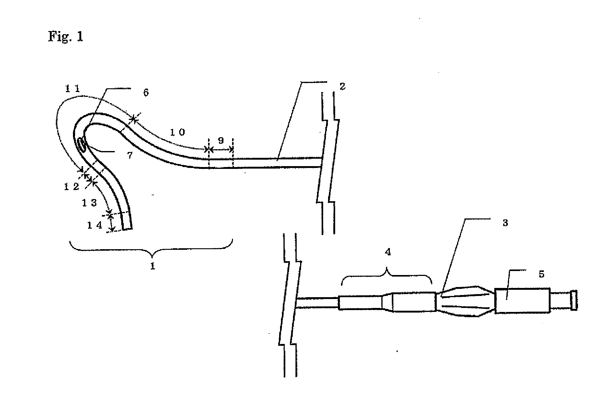
[0113]A composite tube having an external diameter of 2.67 mm, an inner diameter of 2.26 mm, and a length of 900 mm was prepared by using a metal braid of metal wires of 0.10 mm×0.03 mm prepared from SUS 304 WPB alloy (16 wires / braid). An internal layer of a polytetrafluoroethylene (Polyflon F-207, DAMKIN INDUSTRIES. LTD) and an external layer of a polyamide elastomer (PEBAX6333 SA01 (Shore hardness: 63D), ATOFINA) was formed by switched extrusion, to give a proximal shaft.

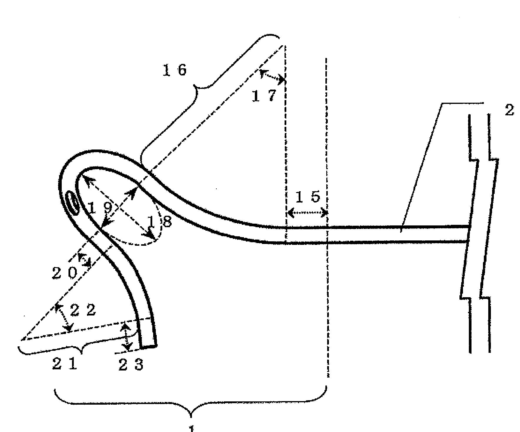
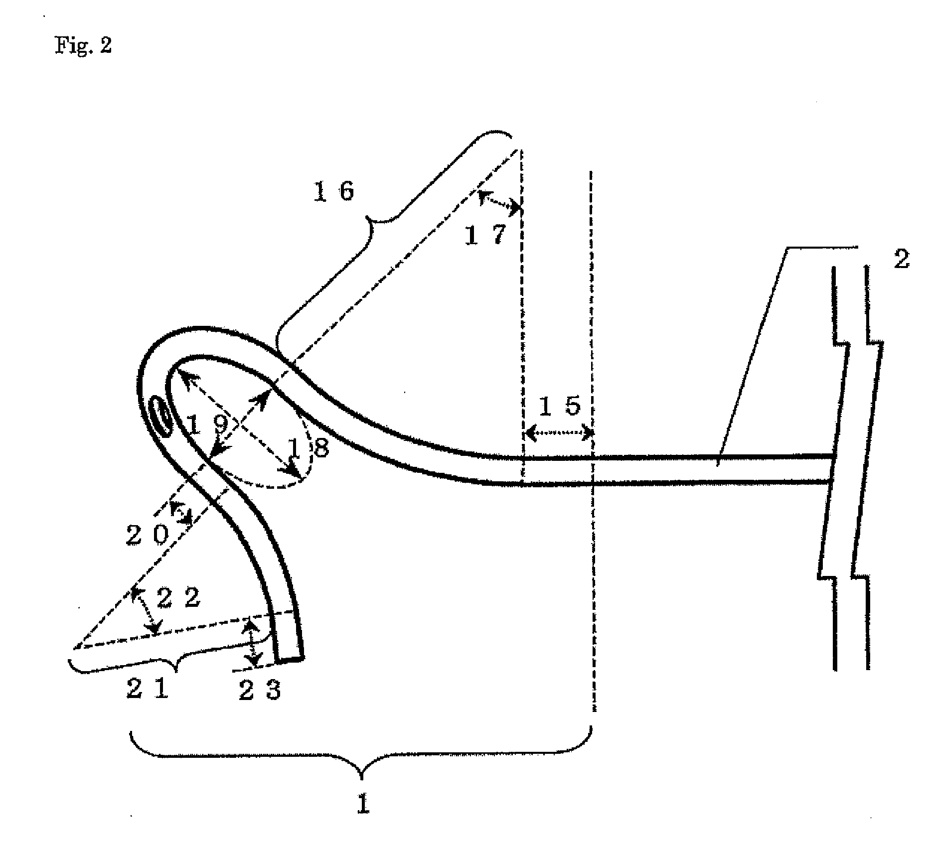
[0114]A polyamide elastomer (PEBAX4033 SA01 (Shore hardness: 40D), ATOFINA) and barium sulfate were extruded biaxially into pellets. The barium sulfate content in the pellet was 40 wt %. A tube having an external diameter of 2.60 mm, an internal diameter of 1.85 mm, and a length of 300 mm was prepared by extrusion molding by using the pellets thus prepared. The tube prepared was placed in the grooves (width and depth: 3.1 mm) on a SUS304 alloy plate: one for the first straight region having a length L1 of 10 mm, c...

example 2

[0116]A blood removal catheter was prepared in a similar manner to Example 1, except that L1 was changed to 50 mm, R1 to 70 mm, θ1 to 40°, A1 to 15 mm, B1 to 11 mm, L2 to 15 mm, R2 to 25 mm, θ2 to 50°, and L3 to 10 mm, and a circular opening having a diameter of 1.8 mm was formed.

example 3

[0117]A blood removal catheter was prepared in a similar manner to Example 1, except that the external diameter of the composite tube was changed to 3.33 mm, the internal diameter to 2.72 mm, the tube external diameter to 3.00 mm, and the internal diameter to 2.25 mm, L1 was changed to 100 mm, R1 to 60 mm, 01 to 50°, A1 to 15 mm, B1 to 11 mm, L2 to 5 mm, R2 to 20 mm, θ2 to 30°, and L3 to 5 mm, and a round polytetrafluoroethylene rod (external diameter: 2.20 mm) was inserted into the tube lumen during molding.


PUM


Abstract

A catheter for blood removal that is to be provided in the coronary sinus via the inferior vena cava to remove the blood in the coronary sinus from the body wherein: the catheter for blood removal has a straight back end shaft, a curved front end shaft connected in the front end side of the back end shaft, a hub connected in the back end side of the back end shaft and a blood removal lumen extending from the back end of the catheter for blood removal to the front end thereof; the front end shaft comprises a first straight part, a first curve part following the first straight part, a second curve part following the first curve part, a second straight part following the second curve part, a third curve part following the second straight part and a third curve part following the third straight part.

Description

TECHNICAL FIELD[0001]The present invention relates to a blood removal catheter used in medical applications, in particular to a blood removal catheter for removing blood containing a contrast medium locally administered to coronary artery from coronary sinus temporarily out of the body.BACKGROUND ART[0002]Angioplasty (PTA: Percutaneous Transluminal Angioplasty or PTCA: Percutaneous Transluminal Coronary Angioplasty) of improving blood flow in peripheral vessels by expanding a stenosis or occlusion site, for example with a balloon catheter, when stenosis or occlusion occurs in vascular systems including blood vessel or when blood vessel is obstructed by thrombus, has been practiced frequently in many medical institutions and thus practiced routinely in therapies of this kind of diseases.[0003]Along with progress of DCA (Directional Coronary Atherectomy) and devices such as Rotor Brator, atherectomy therapy of dissecting atheroma by using a catheter is also practiced. In addition, dev...

Claims


Application Information

Patent Timeline
Patent Type & Authority Applications(United States)
IPC IPC(8): A61M25/00
CPCA61M25/0041A61M25/0052A61M25/0054A61M2025/0078A61M25/0108A61M2025/0063A61M25/007
Inventor MICHISHITA, ICHIRONISHIDE, TAKUJI
Owner KANEKA CORP
Why Eureka
Try Eureka