Control system for internal combustion engine

a control system and internal combustion engine technology, applied in the direction of electric control, machines/engines, instruments, etc., can solve the problems of inability to accurately estimate the amount of exhaust gas recirculation, the robustness of the nox emission amount cannot be improved, and the detection value is difficult to determine. the effect of correct value and robustness

Active Publication Date: 2009-07-30
HONDA MOTOR CO LTD
View PDF5 Cites 32 Cited by
  • Summary
  • Abstract
  • Description
  • Claims
  • Application Information

AI Technical Summary

Benefits of technology

[0022]With this configuration, the engine state parameter is calculated using the self-organizing map for calculating the estimated exhaust gas recirculation amount, and the control amount of the swirl control means is calculated according to the calcula

Problems solved by technology

On the other hand, since the regulation of the NOx emission amount is very strict especially in the United States, it is necessary to surely maintain the NOx emission amount below the regulation value for a long period of time.
Accordingly, the robustness of the NOx emission amount cannot be improved.
However, it is difficult to accurately estimate the exhaust gas recirculation amount, using maps or tables which are previously set to calculate the exhaust gas recirculation amount, or using a physical model of the engine, since the exhaust gas recirculation amount is influenced by various factors, such as the boost pressure, the fuel injection amount, and the intake pressure.
Therefore, even if an exhaust gas recirculation amount sensor is provided to detect the exhaust gas recirculation amount, it is difficult to determine whether or not the detected value is a proper value, or whethe

Method used


Image

  • Control system for internal combustion engine
  • Control system for internal combustion engine
  • Control system for internal combustion engine

Examples


first embodiment

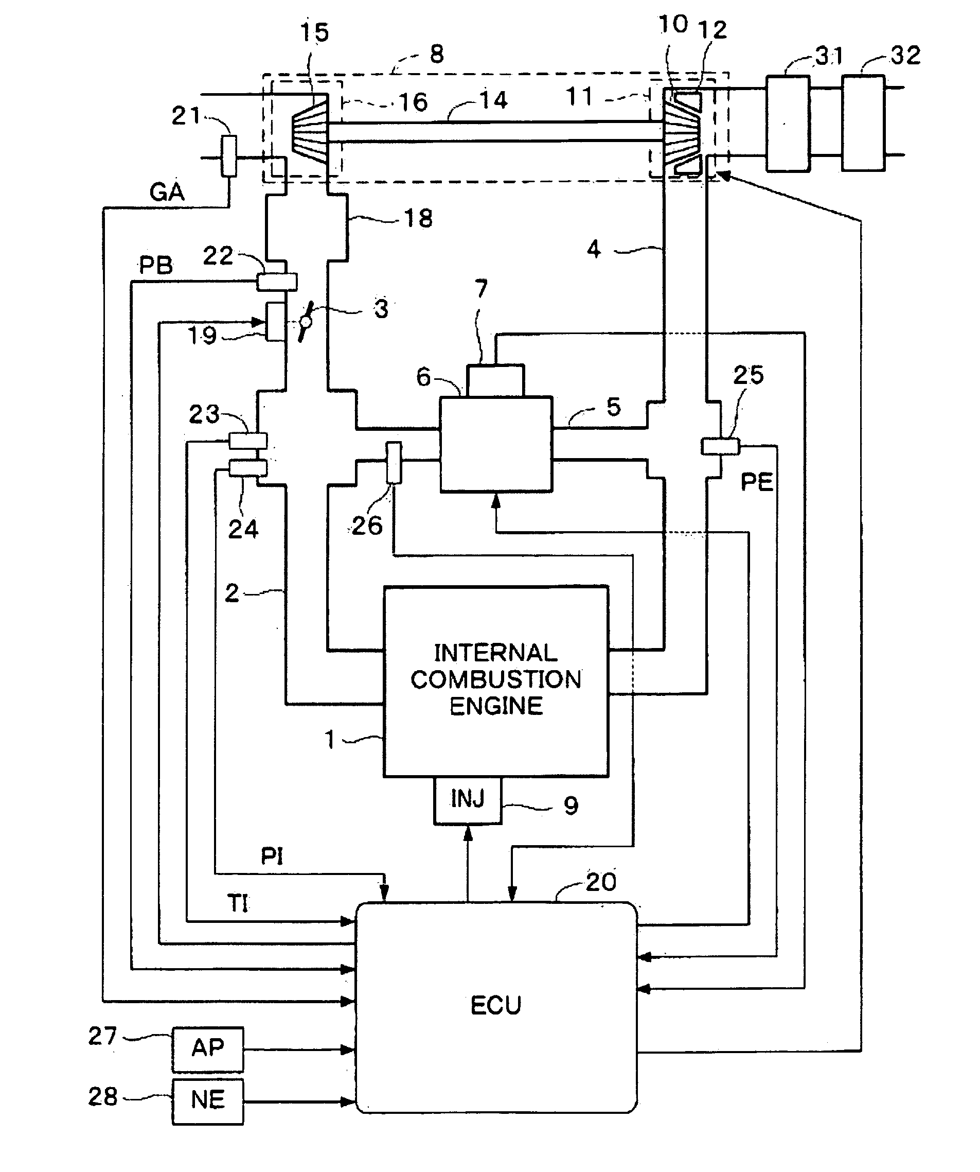
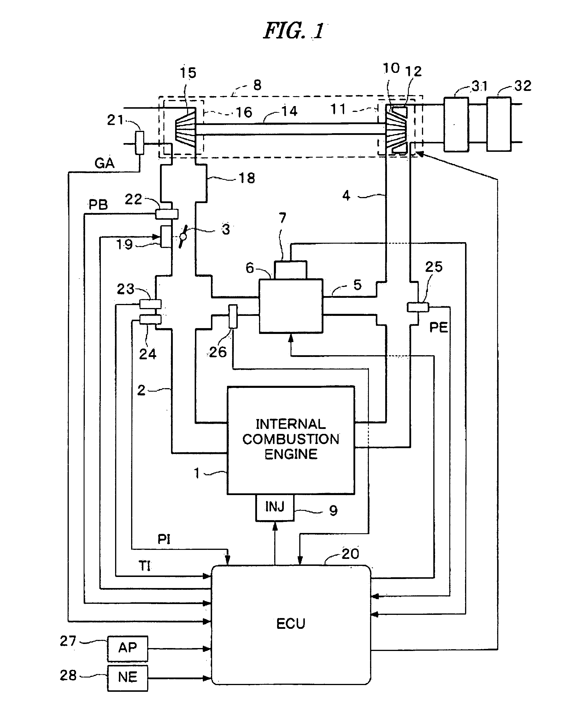
[0061]FIG. 1 is a schematic diagram showing a configuration of an internal combustion engine and a control system therefor according to a first embodiment of the present invention. The internal combustion engine 1 (hereinafter referred to as “engine”) is a diesel engine wherein fuel is injected directly into the cylinders. Each cylinder is provided with a fuel injection valve 9 that is electrically connected to an electronic control unit 20 (hereinafter referred to as “ECU”). The ECU 20 controls a valve opening timing and a valve opening period of each fuel injection valve 9.

[0062]The engine 1 has an intake pipe 2, an exhaust pipe 4, and a turbocharger 8. The turbocharger 8 includes a turbine 11 and a compressor 16. The turbine 11 has a turbine wheel 10 rotationally driven by the kinetic energy of exhaust gases. The compressor 16 has a compressor wheel 15 connected to the turbine wheel 10 via a shaft 14. The compressor wheel 15 pressurizes (compresses) the intake air of the engine 1...

second embodiment

[0120]In this embodiment, the emission amount of NOx, which is applied to a calculation of an amount of NOx trapped in the lean NOx catalyst 31, is corrected according to the correlation parameter a(k). The points that are different from the first embodiment will be described below.

[0121]FIG. 13 is a flowchart of the fuel injection control process in this embodiment. Steps S41 to S44, S46, S47, S49, S52 and S53 shown in FIG. 13 perform the same processes as corresponding steps S11 to S14, S16, S17, S19, S20, and S21 shown in FIG. 4.

[0122]In step S45, the state determination process of the lean NOx catalyst shown in FIG. 15 is performed. In step S61 of FIG. 15, an estimated NOx emission amount NOxhat is calculated using a self-organizing map (hereinafter referred to as “NOx emission amount SOM”) for calculating the NOx emission amount. The NOx emission amount SOM is set corresponding to the reference engine by the same method as that for the self-organizing map for calculating the es...

third embodiment

[0145]FIG. 20 is a schematic diagram showing a configuration of an internal combustion engine and a control system therefor according to the present embodiment. In this embodiment, the exhaust gas recirculation amount sensor 26 is not provided, and an air-fuel ratio sensor 30 is provided in the exhaust pipe 4 immediately downstream of the engine 1. The air-fuel ratio sensor 30 detects an air-fuel ratio AF of an air-fuel mixture in the combustion chamber by detecting an oxygen concentration in the exhaust gases, and supplies a detection signal to the ECU 20. The configuration shown in FIG. 20 is the same as that shown in FIG. 1, except for the above-described point.

[0146]In this embodiment, a state determination of the exhaust gas recirculation control and / or the boost pressure control is performed using the EGR amount SOM, without using the exhaust gas recirculation amount sensor. A distance parameter Discave is calculated as a parameter indicative of the determined control state, a...


PUM


Abstract

A control system for an internal combustion engine is disclosed. In the control system, an engine state parameter is calculated using a self-organizing map for calculating a predetermined output parameter according to at least one engine operating parameter which indicates an operating condition of said engine. The engine state parameter indicates an engine state which is relevant to the predetermined output parameter.

Description

BACKGROUND OF THE INVENTION[0001]1. Field of the Invention[0002]The present invention relates to a control system for an internal combustion engine, and particularly to a control system that determines an engine state which changes due to characteristic variation in mass-produced engines or aging of the engine.[0003]2. Description of the Related Art[0004]Japanese Patent Laid Open No. 2006-250120 (JP'120) discloses a fuel injection control apparatus for a diesel engine. According to this apparatus, a main fuel injection is performed in one combustion cycle with a plurality of divided injections (e.g., two injections), and a dividing ratio of amounts of fuel injected in the divided fuel injections (e.g., a ratio of the fuel amount of the first injection to the fuel amount of the second injection) is changed according to the engine load. With this method, deterioration of the fuel consumption rate and an increase in an amount of generated soot are suppressed when enriching the air-fuel...

Claims


Application Information

Patent Timeline
IPC IPC(8): F02D45/00
CPCF02D41/0072F02D41/1405F02D41/1462F02D41/22F02D41/402Y02T10/47F02D2041/0075F02D2200/0406F02D2200/0806Y02T10/44F02D2041/0015Y02T10/40
Inventor BOTTCHER, JORGFISCHER, MICHAELYASUI, YUJI
Owner HONDA MOTOR CO LTD
Why Eureka
Try Eureka