
Self-tapping biocompatible interference bone screw

a biocompatible, bone screw technology, applied in the field of soft tissue or bone-to-bone fixation devices, can solve problems such as interfering bone graft fit, and achieve the effects of reducing confusion, improving interference screw pull-out strength, and increasing density

Active Publication Date: 2009-08-06
CAYENNE MEDICAL INC
View PDF17 Cites 87 Cited by
  • Summary
  • Abstract
  • Description
  • Claims
  • Application Information

AI Technical Summary

Benefits of technology

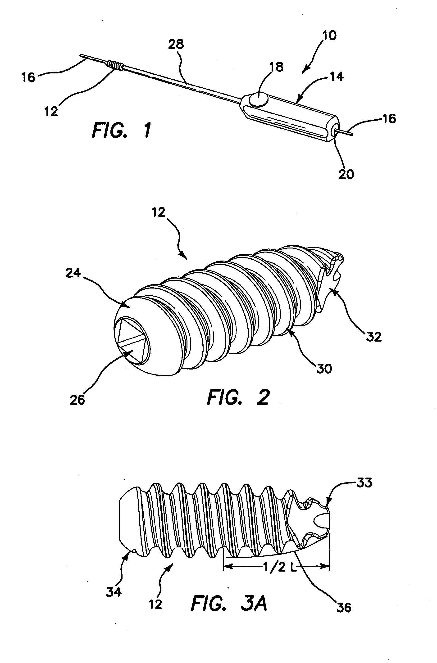
[0011]In conjunction with the screw, a reusable insertion and positioning tool allows the surgeon to drive the screw into place while guiding it over a flexible nitinol guide wire. The screw is inserted into the bone by the driver in a clockwise rotation. The interference fit between the bone graft and tunnel wall occurs as the thread of the screw forwardly propels the screw body into the bone. The minor diameter of the screw acts as the interfering body between either the soft-tissue or bone graft and the tunnel wall essentially press fitting the bodies together and preventing the graft from sliding through the tunnel without significant required force. In the case of BPTB procedures, the screw is inserted against the boney side of the BPTB graft, allowing the soft tissue side on the alternate lateral half of the BPTB graft to osteointegrate within the surrounding bone. Aside from the body of the screw providing a pure interference fit between the bone tunnel and graft, the screw's thread provides additional fixation of the graft by essentially tacking it into position within the bone tunnel. Depending on the cut depth of the thread (the difference between the major and minor radius of the screw) the amount of bone purchase the screw thread has grasped can be controlled.
[0012]The use of the device is straightforward, eliminating potential for confusion that may arise when using other bone screw fixation technologies. No additional accessories or steps are required other than the screw, driver, and optional guide wire. The only step required in preparation for graft fixation is to locate and drill tunnels within the femur and tibia.
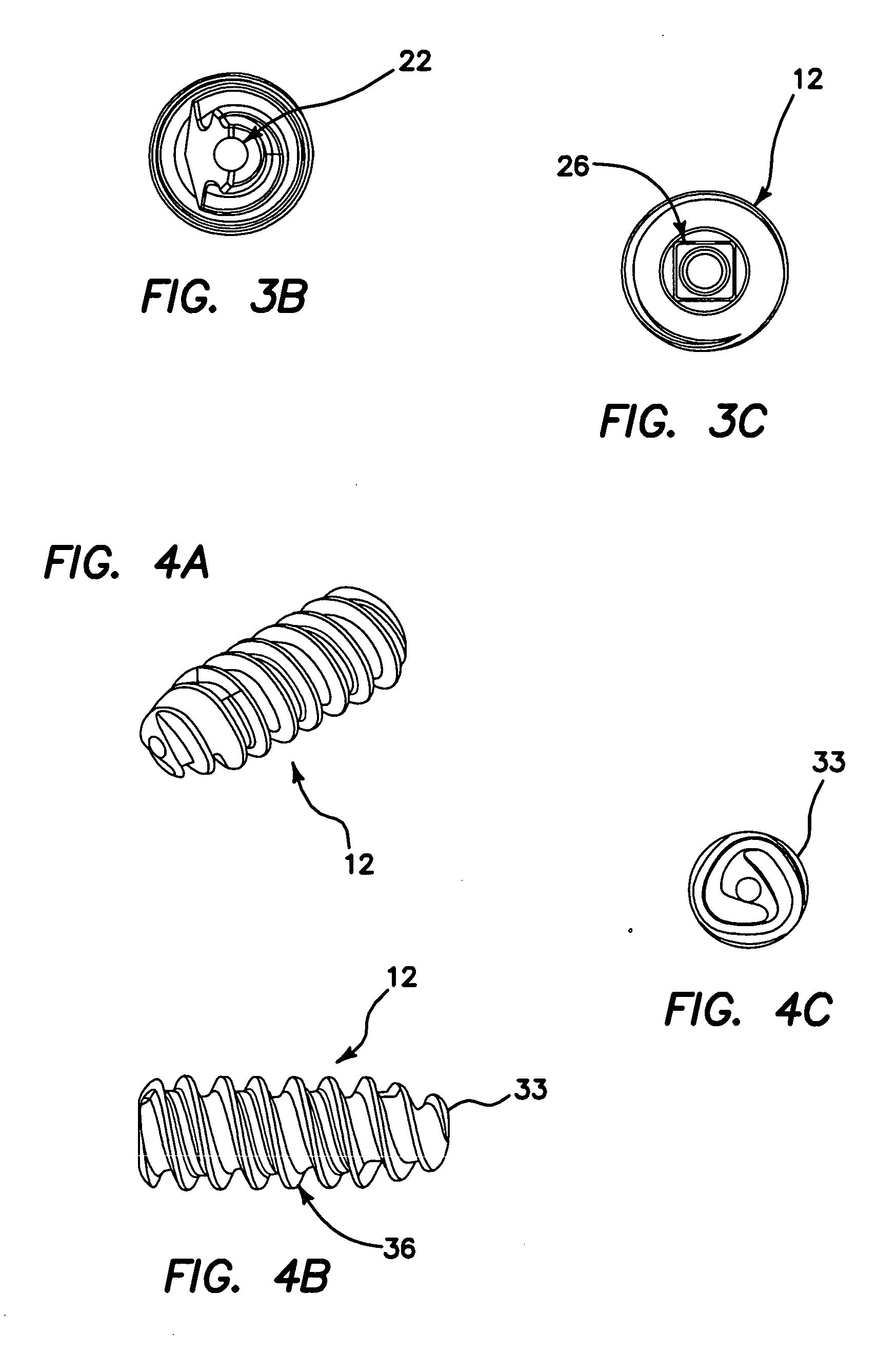
[0013]The narrow tip of the inventive interference screw allows it to be used in most situations without requiring dilation or notching at the implant site. Furthermore, the durability of the PEEK material in combination with its angled tip design allows it to be implanted into harder bone without requiring the use of a tap. The tapless / notchless screw design was verified by measuring the ease of insertion during implantation into porcine bone, having a higher density than human bone. The predicate device chosen for the present device validation before the FDA required the use of a separate tapping step in order perform its installation whereas the inventive screw requires no additional preparatory steps at the implantation site
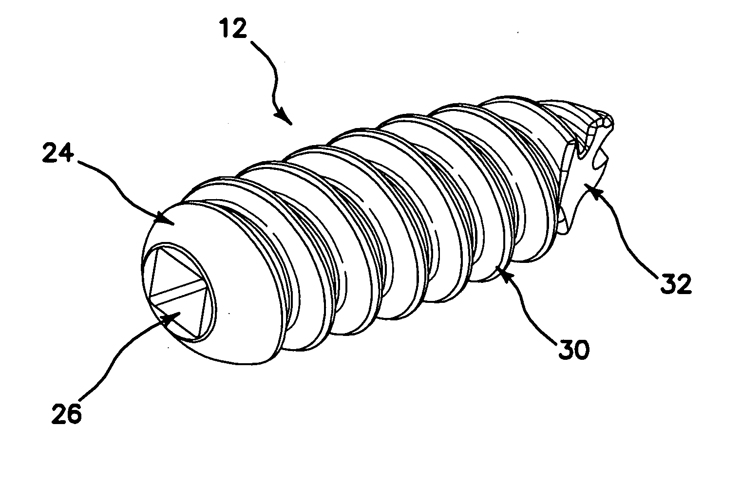
[0014]More particularly, in one aspect of the invention, there is provided a biocompatible interference screw for soft tissue or bone-to-bone fixation, which comprises a preferably rounded screw head for permitting a user to insert the screw to a desired location within a patient's body. The inventive screw further comprises a screw body extending from the screw head to a distal tip of the screw. The screw body has an outer surface, and comprises polyether-ether-ketone (PEEK) material. Advantageously, the body outer surface has a textured surface finish for substantially improving pull-out strength of the interference screw. The textured surface finish is textured, in preferred embodiments, with a minimum of approximately 16 micro inches of surface roughness, and is bead blasted. The screw head comprises a tapered square keyhole for receiving a distal end of a driver instrument. The screw comprises a series of threads, which have a relatively smooth profile, in order to prevent graft tissue laceration as the screw is being inserted. The distal tip of the screw body preferably comprises a narrow tip, and a distal end of the screw body is preferably angled inwardly toward the narrow distal tip.

Problems solved by technology

The interference fit between the bone graft and tunnel wall occurs as the thread of the screw forwardly propels the screw body into the bone.

Method used


Image

  • Self-tapping biocompatible interference bone screw
  • Self-tapping biocompatible interference bone screw
  • Self-tapping biocompatible interference bone screw

Examples


Embodiment Construction

[0029]Referring now more particularly to the drawings, there is shown in FIG. 1 an interference screw anchoring system 10, which comprises an interference screw 12, a driver 14, and a guide wire 16, along which the driver 14 and interference screw 12 may be guided to a desired operative site.

[0030]The inventive interference screw 12 is intended for the bone-patellar tendon-bone reconstruction of the ACL, but may be used in other applications as well. During an ACL reconstruction procedure, BPTB grafts are fixed to the femur and tibia, utilizing the inventive interference screw 12. BPTB grafts are typically harvested from the patient's ipsilateral leg, but cadaveric grafts are also acceptable. The interference screw is packaged sterile, and is designed to provide compression of a BPTB graft within the femoral and tibial tunnels at the procedural site. The driver 14, and other system components comprising the instrument set 10 are designed to be reusable. A disposable kit provided wit...


PUM


Abstract

A biocompatible interference screw for soft tissue or bone-to-bone fixation comprises a screw body extending from a screw head to a distal tip of the screw. The screw body has an outer surface, and comprises polyether-ether-ketone (PEEK) material. Advantageously, the body outer surface has a textured surface finish for substantially improving pull-out strength of the interference screw. The textured surface finish is textured, in preferred embodiments, with a minimum of approximately 16 micro inches of surface roughness. The screw head comprises a tapered square keyhole for receiving a distal end of a driver instrument. The screw comprises a series of threads, which have a relatively smooth profile, in order to prevent graft tissue laceration as the screw is being inserted. The distal tip of the screw body comprises a narrow tip, and a distal end of the screw body is angled inwardly toward the narrow distal tip.

Description

[0001]This application claims the benefit under 35 U.S.C. 119(e) of the filing date of Provisional U.S. Application Ser. No. 61 / 025,250, entitled Self Tapping Biocompatible Interference Bone Screw, filed on Jan. 31, 2008, which application is expressly incorporated herein by reference, in its entirety.BACKGROUND OF THE INVENTION[0002]The present invention relates to soft tissue or bone-to-bone fixation devices, and more particularly to those comprised from the biocompatible polymer polyether-ether-ketone (PEEK).[0003]Current biocompatible polymeric screws, such as those comprised of poly-1-lactide acid (PLLA) or poly-lactide acid (PLA), lack the durability to be inserted into cancellous bone without the additional step of manually tapping the implant site intended to receive the bone screw with a surgical bone tap. Though screws created from these materials possess the desired characteristics of radiolucency and MRI compatibility, the additional procedural step of tapping is often d...

Claims


Application Information

Patent Timeline
IPC IPC(8): A61B17/86
CPCA61B17/8615A61B17/8635A61B17/864A61B17/888A61B17/861A61F2002/0858A61F2002/0882A61B17/8605A61F2/0811
Inventor HOOF, JORDAN A.BAIRD, KEVIN N.HARPER, DEREK J.
Owner CAYENNE MEDICAL INC
Learn More