Electrochromic layer and devices comprising same

a technology of electrochromic layer and electrode, which is applied in the field of electrochromic layer and devices comprising it, can solve the problems of non-uniform thickness of solution layer, oxidized form of anodic and reduced cathodic electrochromic materials in such devices, and non-uniform thickness in the solution layer

Inactive Publication Date: 2009-08-13
TONAR WILLIAM L +4
View PDF2 Cites 1 Cited by
  • Summary
  • Abstract
  • Description
  • Claims
  • Application Information

AI Technical Summary

Benefits of technology

[0051] Because they are free-standing gels and surprisingly, in many cases, do not significantly weep, the electrochromic layers of the invention avoid problems due to hydrostatic pressure of fluids in large-area electrochromic devices in which the layers of the invention are the media of reversibly variable transmittance.

Problems solved by technology

One of the problems associated with such devices is that of segregation.
When operated continuously for long periods of time, the oxidized form of the anodic and reduced form of the cathodic electrochromic materials in such devices tend to segregate.
Thickened or gelled electrochromic solutions in the art suffer from a number of shortcomings that have restricted or prevented the practical application of electrochromic devices to provide variable transmittance or variable reflectance in a number of contexts.
Thus, in these large area apparatus, hydrostatic pressure makes solution-phase electrochromic devices susceptible to breakage, for example due to rupture of seals holding walls of the electrochromic device together.
Even when there is not breakage, the hydrostatic pressure causes bowing out of the walls of the electrochromic device, which results in non-uniform thickness in the solution layer and undesirably non-uniform coloring and clearing during operation of the device.
Because solutions thickened by prior art methods (e.g., Shelepin et al., supra; '108 patent) are not free-standing gels, the fluid in them is not entrapped in a polymer matrix and, consequently, still exerts undesirable hydrostatic pressure and concomitant device-breaking or device-distorting forces in large area devices.
However, there are limitations with in situ polymerization.
If polymerization and crosslinking takes place in the device, there is a significant amount of shrinkage in the polymer solution.
This shrinkage causes the solid polymer to crack, craze and form voids, all of which adversely affects the usefulness of the final device.
Furthermore, the detrimental effects will sometimes not be noticed for some time since polymerization and crosslinking can occur over a period of weeks.
If, on the other hand, only polymerization, and no crosslinking takes place, a “free standing” polymer will not form and hydrostatic pressure will build up and adversely affect the operability of the final device.
Difficulties arise with UV curing because not all the radicals are consumed to initiate a reaction and / or self-react and are therefore present in the device after “final cure” of the polymer gel.
In addition, the electrochromic materials may interfere with light absorption or initiation and may inhibit or retard the polymerization process.
Thus UV curing is not presently preferred.
Finally, it would be desirable if such a layer would not shrink to such an extent that the usefulness of the final device is compromised.
However, electrochromic layers which would have such favorable structural, flow and electrode-layer-adherence properties would be chemically complex.
Consequently it is not straightforward to provide such an electrochromic layer that retains other characteristics that are important for practical applications of media of reversibly variable transmittance in electrochromic devices, especially such devices which are desirably solution-phase, single-compartment and self-erasing.
For example it is undesirable to have significant polymer formation continuing in an electrochromic layer inside a device for more than a few days, because the layer may shrink with time or the performance characteristics (e.g., color in the clear state, coloring and clearing times, uniformity of coloring) of the layer and the device that includes the layer would then undesirably change over time.

Method used


Image

  • Electrochromic layer and devices comprising same
  • Electrochromic layer and devices comprising same
  • Electrochromic layer and devices comprising same

Examples


example 1

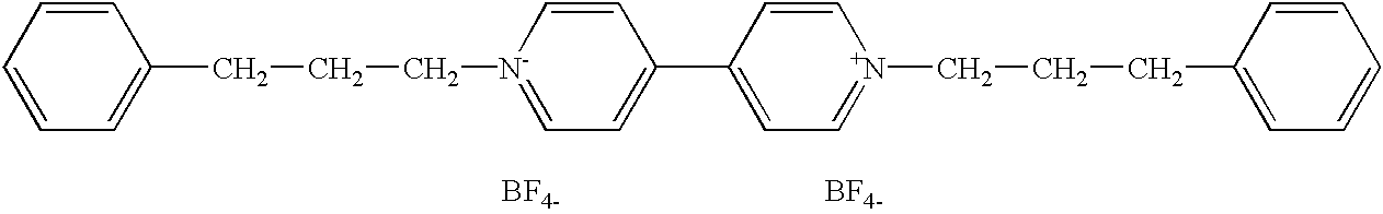
Synthesis of 1,1′-di(3-phenyl(n-propyl))-4,41-dipyridinium Difluoroborate

[0083]

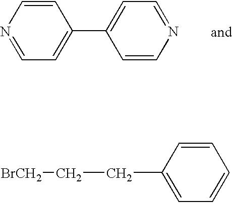
[0084] The compound was made starting with the known compounds, 4,4′-bipyridine and 1-bromo-3-phenylpropane, of formulas

respectively. A solution of 10 g of 4,4-bipyridine and 38.9 ml of 1-bromo-3-phenylpropane was dissolved in 150 ml of acetonitrile. The solution was refluxed for about 24 hours. The yellow precipitate was filtered off by vacuum filtration. The precipitate was then slurried in an excess of acetone and again vacuum filtered. The yellow precipitate was then dried at 60° C.

[0085] The dried, yellow precipitate was dissolved in 600 ml of warm water and the solution was carbon treated and filtered. To this solution an aqueous solution of sodium fluoroborate was added to provide a slight excess of fluoroborate ions. The solution was heated to about 90° C. and was treated with carbon. The hot solution was filtered and cooled.

[0086] Upon cooling, white crystals and yellow precipitate formed w...

example 2

Electrochromic Layer Comprising a Polymer Matrix from Polyester Polyol Chains Joined by Isocyanates Reacting with Hydroxyls

[0089] An electrochromic layer comprising a polymer matrix made by linking polyester polyol chains through hydroxyl groups of the chains was prepared as follows. 8.0 g of 0.08 M 1,1′-dibenzyl-2,2′,6,6′-tetramethyl-4,4′-bipyridinium difluoroborate in propylene carbonate, 8.0 g 0.08 M 5,10-dihydro-5,10-dimethylphenazine in propylene carbonate, 3.52 g of Desmophen 1700 (a polyester polyol sold by Miles, Inc., Pittsburgh, Pa., USA, made from adipic acid and diethylene glycol, having an average molecular weight of 2550 daltons and an hydroxyl functionality of 2) and 0.48 g of Desmodur N-100 (a polymer of hexamethylene diisocyanate comprising biuret groups, having an isocyanate functionality near 3, sold by Miles Inc.) and one drop of catalyst (dibutyltin dilaurate, Aldrich, Milwaukee, Wis.) were mixed in a glass vial. The electrochromic layer was gelled by baking th...

example 3

Antiscattering Qualities of an Electrochromic Layer Comprising a Polymer Matrix from Polyester Polyol Chains Joined by Isocyanates Reacting with Hydroxyls

[0092] An electrochromic device containing a polyurethane electrochromic layer was prepared as follows. 48.0 g of 0.08 M 1,1′-dibenzyl-2,2′,6,6′-tetramethyl-4,4′-bipyridinium difluoroborate in propylene carbonate, 48.0 g 0.08 M 5,10-dihydro-5,10-dimethylphenazine in propylene carbonate, 21.12 g of Desmophen 1700, 2.88 g of Desmodur N-100, and 2 drops of catalyst (dibutyltin dilaurate, Aldrich, Milwaukee, Wis.) were mixed together and used to fill an electrochromic mirror as detailed in Example 2. Then polymer matrix formation (gelling) was carried out by heating to 85° C. for 25 minutes.

[0093] Adhesive tape was placed on the back of the mirror. A 1 kg metal sphere was dropped on the mirror from a height of approximately 1 m. Inspection revealed that no electrochromic solution had leaked from the broken mirror and there was no evi...


PUM

PropertyMeasurementUnit
temperatureaaaaaaaaaa
molecular weightaaaaaaaaaa

Abstract

The present invention provides improved electrochromic layers, which comprise polymeric matrices with electrochromic solutions interspersed therein. Varying an electrical potential difference across a layer of the invention results in reversible variation in the transmittance of light across the layer because of electrochemical processes in the electrochromic solution of the layer. The invention further provides electrochromic devices, in which the electrochromic layers of the invention provide reversibly variable transmittance to light, and various apparatus in which the devices of the invention provide light-filtering or light-color modulation. Such apparatus include windows, including those for use inside and on the outside walls of buildings and in sunroofs for automobiles, and variable reflectance mirrors, especially rearview mirrors for automobiles.

Description

TECHNICAL FIELD [0001] The present invention relates to electrochromic devices which provide light-filtering, color-modulation, or reflectance-modulation in apparatus such as variable-transmittance windows, variable-reflectance mirrors; and display devices which employ such light-filters or mirrors in conveying information. [0002] More particularly, the invention concerns the electrochromic medium in such an electrochromic device. The electrochromic medium undergoes a change in transmittance to light, and a concomitant change in color, when an electrical potential difference is imposed across it in the device. [0003] The invention relates to novel electrochromic media which address a number of problems presented by electrochromic devices with electrochromic media which comprise fluids or solutions. The media of the invention occur in electrochromic devices of the invention as electrochromic layers occupying the space between electrode layers of the devices. A medium of the invention...

Claims


Application Information

Patent Timeline
Patent Type & Authority Applications(United States)
IPC IPC(8): G02F1/00G02F1/1503
CPCG02F1/1521G02F2001/1512G02F2001/1502G02F1/1503G02F2001/15145
Inventor TONAR, WILLIAM L.BYKER, HARLAN J.ROBERTS, KATHY E.ANDERSON, JOHN S.ASH, KEVIN L.
Owner TONAR WILLIAM L
Why Eureka
Try Eureka