System for treating carbon dioxide, and method for storing such treated carbon dioxide underground

a carbon dioxide and treatment system technology, applied in the direction of separation processes, nuclear engineering, wellbore/well accessories, etc., can solve the problems of difficult to achieve the 6% reduction goal, unsuitability for storing carbon dioxide underground, and high cost of further reducing carbon dioxide emissions, so as to achieve efficient carbon dioxide bubble production and prevent upward diffusion of carbon dioxid

Active Publication Date: 2009-08-13
MIZUHO RES & TECH LTD
View PDF4 Cites 39 Cited by
  • Summary
  • Abstract
  • Description
  • Claims
  • Application Information

AI Technical Summary

Benefits of technology

[0016]The method of the present invention for storing carbon dioxide underground has the following effect. When carbon dioxide—in the form of fine bubbles or as a supercritical fluid—is dissolved into groundwater that has been pumped up from a deep aquifer, about 50 kg of carbon dioxide becomes dissolved in 1 m3 (1000 kg by weight) of water, under high pressure and at a high temperature in the deep aquifer. Carbon dioxide in the form of fine bubbles can be diffused more widely in a deep aquifer than can a supercritical fluid that becomes solidified (becomes a plume) after being injected into a deep aquifer. In addition, the area of contact between groundwater and carbon dioxide in the form of fine bubbles is significantly larger than the area of contact between groundwater and a supercritical fluid. Therefore, the rate of solution of the carbon dioxide in the form of fine bubbles into groundwater is several hundred to several thousand times faster than rate of solution of a supercritical fluid into groundwater. Also, a caprock layer (a sealing layer or an impermeable layer) often exists in places like an oil field. Even where there is no caprock layer (a sealing layer or an impermeable layer), the fine bubbles of carbon dioxide go into gaps between the soil particles, and become stabilized. The weight of carbon dioxide under 1 atm and at 0° C. is 1.98 kg / m3. So, for example, if 50 kg of carbon dioxide is to be dissolved in 1 m3 of water, it is possible to stabilize about 25 m3 of carbon dioxide in 1 m3 of the groundwater.
[0017]The invention described has the following effect. A cation-forming material (e.g., coal ash, calcium hydroxide, blast-furnace slag, or liquid glass) is dissolved in the injection water. The injection water is then injected into the top portion of the aquifer, at a place that is above the place where the gas-liquid mixture has been injected. Thus, the fine bubbles injected into the deep aquifer react with cations, and, as a result, a barrier of carbonate compound is created. Therefore, upward diffusion of carbon dioxide is prevented. In other words, an artificial sealing layer is formed.
[0018]The present invention's system described for storing carbon dioxide underground has the following effect. Carbon dioxide is turned into fine bubbles so as to be dissolved in groundwater that has been pumped up from a deep aquifer. Therefore, it is possible to dissolve a larger amount of carbon dioxide—an amount larger than when using a conventional method—into the injection water. In addition, the carbon dioxide that does not become dissolved is mixed with the injection water so as to form a gas-liquid mixture that is fed into the deep aquifer. The fine bubbles go into the gaps between the soil particles, react with minerals in the soil particles, and change into, for example, carbonate minerals. The carbon dioxide is thus stabilized.
[0019]In the invention described, a double pipe is used for the injection well, and therefore it is possible to simultaneously feed both injection water and carbon dioxide to the bottom of the injection well. This leads to instantaneous production of a gas-liquid mixture in the injection well, and there is no need for a special mixing device aboveground.
[0020]The invention described uses a nozzle in which a carbon-dioxide spray pipe is connected with an injection-water spray pipe. As a result, carbon dioxide bubbles can be produced efficiently.

Problems solved by technology

If this continues, it will be difficult to achieve the 6% reduction goal.
Therefore, the cost of further reducing carbon dioxide emissions will be significantly high, which is a problem.
The United States and the European Union are storing carbon dioxide underground as an effective measure for reducing that greenhouse gas, but in Japan, storing carbon dioxide underground is considered unsuitable due to Japan's geological conditions as well as the frequent earthquakes that occur in this country.
However, in Japan it is difficult to find a place that is economical and suitable for that type of storage.

Method used


Image

  • System for treating carbon dioxide, and method for storing such treated carbon dioxide underground
  • System for treating carbon dioxide, and method for storing such treated carbon dioxide underground
  • System for treating carbon dioxide, and method for storing such treated carbon dioxide underground

Examples


embodiment 1

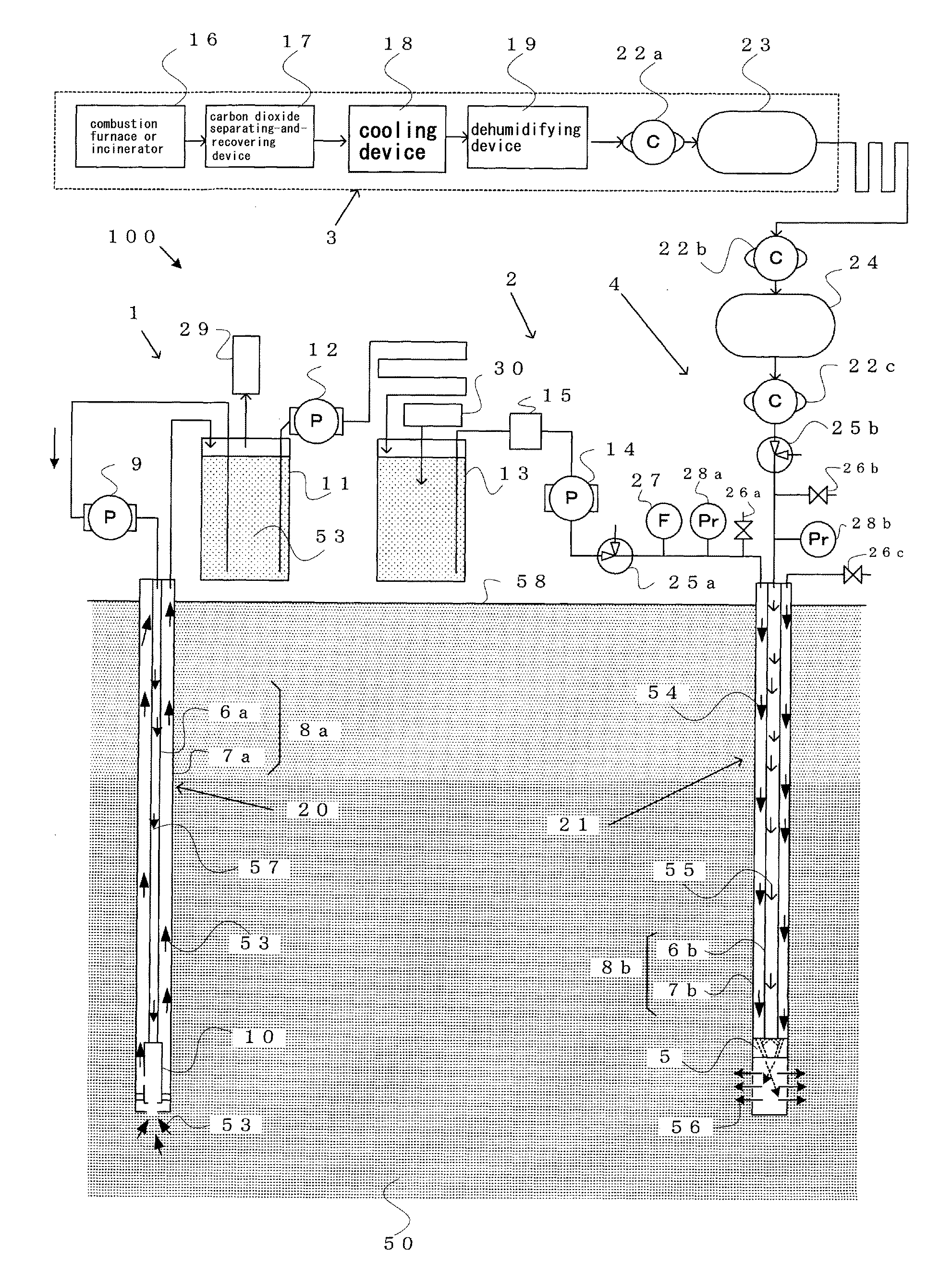
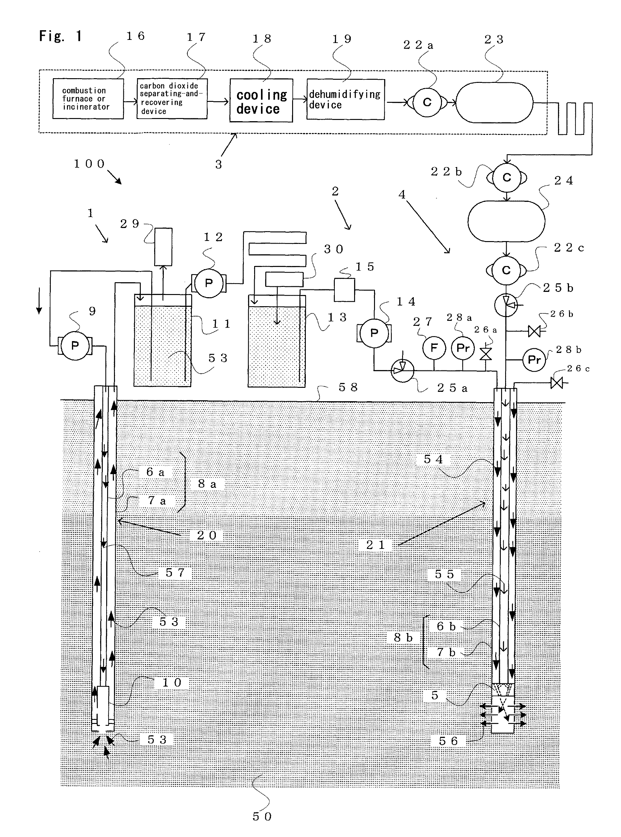
[0085]FIG. 1 shows the constitution of the present invention's system for storing carbon dioxide underground.

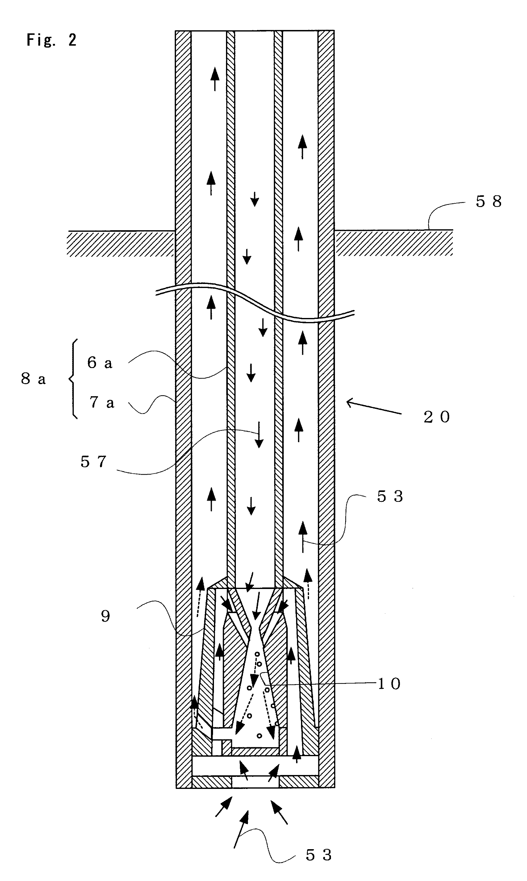
[0086]The carbon-dioxide treating system 100 includes[0087]a pumping well 20 that reaches a deep aquifer 50,[0088]a pump 1 that pumps up groundwater 53 from the pumping well 20,[0089]an injection well 21 that reaches the deep aquifer 50,[0090]a liquid injection device 2 that feeds pumped-up groundwater 53—as injection water 54—into the injection well 21,[0091]a gas injection device 4 that feeds into the injection well 21 carbon dioxide 55 that has been separated and recovered from exhaust gas from an outside plant facility 3, and[0092]a nozzle 5 that changes the carbon dioxide 55 into fine bubbles inside the injection well 21.

[0093]The carbon dioxide 55 is changed into fine bubbles by the nozzle 5, and the fine bubbles are then dissolved in the injection water 54. A gas-liquid mixture 56 of carbon dioxide 55 and injection water 54 is injected into the deep aquifer 50. The pla...


PUM

PropertyMeasurementUnit
depthaaaaaaaaaa
distanceaaaaaaaaaa
heightaaaaaaaaaa

Abstract

The present invention provides a system for treating carbon dioxide, and a method by which such treated carbon dioxide can be stored underground at low cost and with high efficiency. The present invention' method for storing carbon dioxide underground includes: a step for pumping up to the ground groundwater from a pumping well in a deep aquifer, and then producing injection water. Carbon dioxide that has been separated and recovered from exhaust gas from a plant facility is changed into the bubbles. The bubbles are mixed with the injection water, and hereby produces a gas-liquid mixture a step for injecting into. The deep aquifer is injected into the gas-liquid mixture from the injection well. The method preferably further includes a step for dissolving a cation-forming material in the injection water, and a step for injecting the injection water, in which the cation-forming material is dissolved, into the deep acquifer at its top and above the place at which injection water has already been injected.

Description

CROSS-REFERENCE TO RELATED APPLICATIONS[0001]The present Application is based on International Application No. PCT / JP2007 / 062915, filed on Jun. 27, 2007, which in turn corresponds to Japanese Application No. 2006-178345 filed on Jun. 28, 2006, and priority is hereby claimed under 35 USC § 119 based on these applications. Each of these applications are hereby incorporated by reference in their entirety into the present application.FIELD OF THE INVENTION[0002]The present invention relates to the storing underground of carbon dioxide (CO2) that is in exhaust gas generated from a combustion furnace or an incinerator, and more particularly to a method and system for treating carbon dioxide without the need for a facility that changes carbon dioxide into a supercritical fluid.BACKGROUND OF THE INVENTION[0003]As a countermeasure against global warming, it is Japan's duty to reduce, between 2008 and 2012, the emission volume of greenhouse gas by an average of 6% per annum from the level of ...

Claims


Application Information

Patent Timeline
Patent Type & Authority Applications(United States)
IPC IPC(8): B09B5/00F17C3/00C01B32/50
CPCB01D53/1475B01D53/18B01D53/62B01D2257/504Y02C10/14E21B43/164Y02C10/04Y02C10/06E21B41/0064Y02P90/70Y02C20/40
Inventor KOIDE, HITOSHISHINODA, JUNJI
Owner MIZUHO RES & TECH LTD
Why Eureka
Try Eureka