
Chalcopyrite Solar Cell and Manufacturing Method Thereof

a solar cell and chalcopyrite technology, applied in the field of solar cells, can solve the problems of insufficient protection of stainless steel substrate from aggressiveness of hsub>2, inconvenience of peeled mo electrode layer (backside electrode thin film) from corroded stainless steel substrate, etc., and achieves the effects of high flexibility, high conversion efficiency and light weigh

Inactive Publication Date: 2009-08-20
HONDA MOTOR CO LTD
View PDF9 Cites 13 Cited by
  • Summary
  • Abstract
  • Description
  • Claims
  • Application Information

AI Technical Summary

Benefits of technology

[0017]As stated above, in the related arts, in actual circumstances, there is not used a substrate material satisfying high insulating property, easy obtainment, relatively low cost, satisfactory adhesion with respect to Mo electrode layer (lower part electrode thin film), smooth surface, melting point of 600° C. or more, light weight and good flexibility.
[0044]Further, the silicon based smoothing layer of SiN or SiO2 is provided, thereby making it possible to smooth micro roughness of the mica substrate coated by ceramic based material to improve adhesion with respect to the binder layer.

Problems solved by technology

As a result, it was impossible to manufacture solar cells having high conversion efficiency.
Moreover, in the technology in which layers (protective layers) of silicon oxide or iron fluoride are respectively formed on upper and lower surfaces of a stainless steel substrate, which is described in the Patent Document 2, it is insufficient to protect the stainless steel substrate from aggressiveness of H2Se gas in the vapor-phase selenization process.
As a result, there was the inconvenience that Mo electrode layer (backside electrode thin film) is peeled from corroded stainless steel substrate, etc.
Further, since the protective layer is separated so that the conductive stainless steel substrate is exposed, it was impossible to introduce scribing process using metallic needle.

Method used


Image

  • Chalcopyrite Solar Cell and Manufacturing Method Thereof
  • Chalcopyrite Solar Cell and Manufacturing Method Thereof
  • Chalcopyrite Solar Cell and Manufacturing Method Thereof

Examples


Embodiment Construction

[0053]Prior to explanation of an example, the surface shape of a laminated mica substrate will be explained. FIGS. 4(A) and 4(B) indicate measurement results of surface shapes at arbitrary two parts of the laminated mica substrate. In FIG. 4, the abscissa indicates position in a lateral direction of the laminated mica substrate, and the ordinate indicates position in a height direction. As the feature of the laminated mica substrate, the maximum altitude difference is extremely sharply changed (the aspect ratio is large). As seen from FIG. 4, the maximum altitude difference of 5 to 6 μm exists within the range of several 10 μm in a lateral direction. It is understood that this cause results from the process for laminated mica. It is understood that since crushed mica is mixed in resin, crushed mica pieces exist on the surface so that the aspect ratio is extremely increased. In this case, surface roughnesses of the laminated mica substrate with respect to measured two parts were expr...


PUM


Abstract

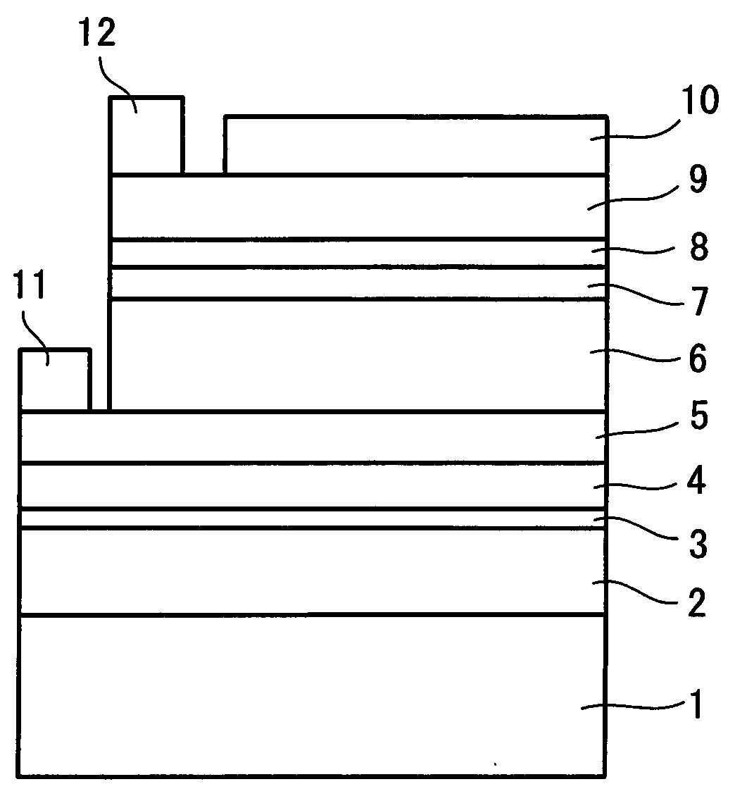
A solar cell having high conversion efficiency and excellent flexibility is realized. A mica substrate or laminated mica substrate is used as substrate 1. The mica and laminated mica have high insulating property and heat resistance temperature, which can be selenized at an appropriate treatment temperature through vapor-phase selenization process, high conversion efficiency and excellent flexibility resultantly suitable for mass-production can be obtained. On the other hand, because the surfaces of the mica and laminated mica have large surface roughnesses, it is impossible to induce leakage to obtain high conversion efficiency in the case where a chalcopyrite based light absorbing layer 6 is simply formed. In the present invention, an intermediate layer 2 of ceramic based material and binder layer 4 are interposed between the mica substrate 1 and a molybdenum electrode 5. By providing the intermediate layer 2 and binder layer 4, surface coating property is enhanced and a solar cell having high conversion efficiency can be realized.

Description

TECHNICAL FIELD[0001]The present invention relates to a solar cell including a light absorbing layer of chalcopyrite compound, and more particularly to a solar cell having high flexibility, suitable for mass-production, and having high conversion efficiency, and a manufacturing method thereof.BACKGROUND ART[0002]Solar cells adapted for receiving rays of light to convert them into an electric energy are classified into solar cells of the bulk system and solar cells of the thin film system depending upon thickness of the semiconductor. Among them, the solar cell of the thin film system is a solar cell in which the semiconductor layer has a thickness lower than several 10 μm to several μm, and is classified into solar cell of the Si thin film system and solar cell of compound thin film system. As the solar cell of the compound thin film system, there are solar cells of the II-VI group compound and solar cells of the chalcopyrite compound, etc. Until now, several solar cells of compound...

Claims


Application Information

Patent Timeline
IPC IPC(8): H01L31/0264H01L31/18
CPCH01L31/022425Y02E10/541H01L31/0749H01L31/0322Y02P70/50
Inventor YONEZAWA, SATOSHIHAYASHIDA, TADASHI
Owner HONDA MOTOR CO LTD
Learn More