

Apparatus for ion nitriding an aluminum alloy part and process employing such apparatus
- Summary
- Abstract
- Description
- Claims
- Application Information
AI Technical Summary
Benefits of technology
Problems solved by technology
Method used
Image

Examples
Embodiment Construction
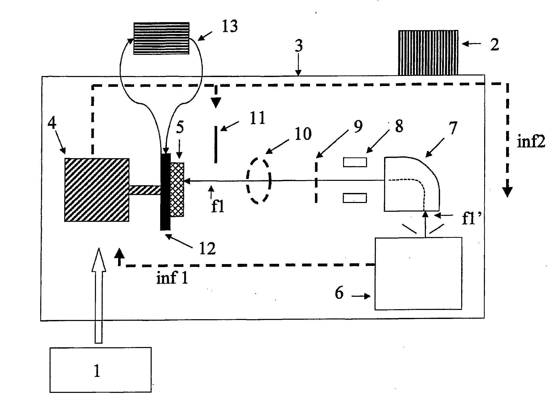
[0018]The object of the invention is to remedy the drawbacks and problems of the techniques described above.
[0019]The invention is directed in particular to an apparatus for implanting ions, particularly nitrogen ions, in an aluminum alloy part in order to improve the mechanical strength of said part.
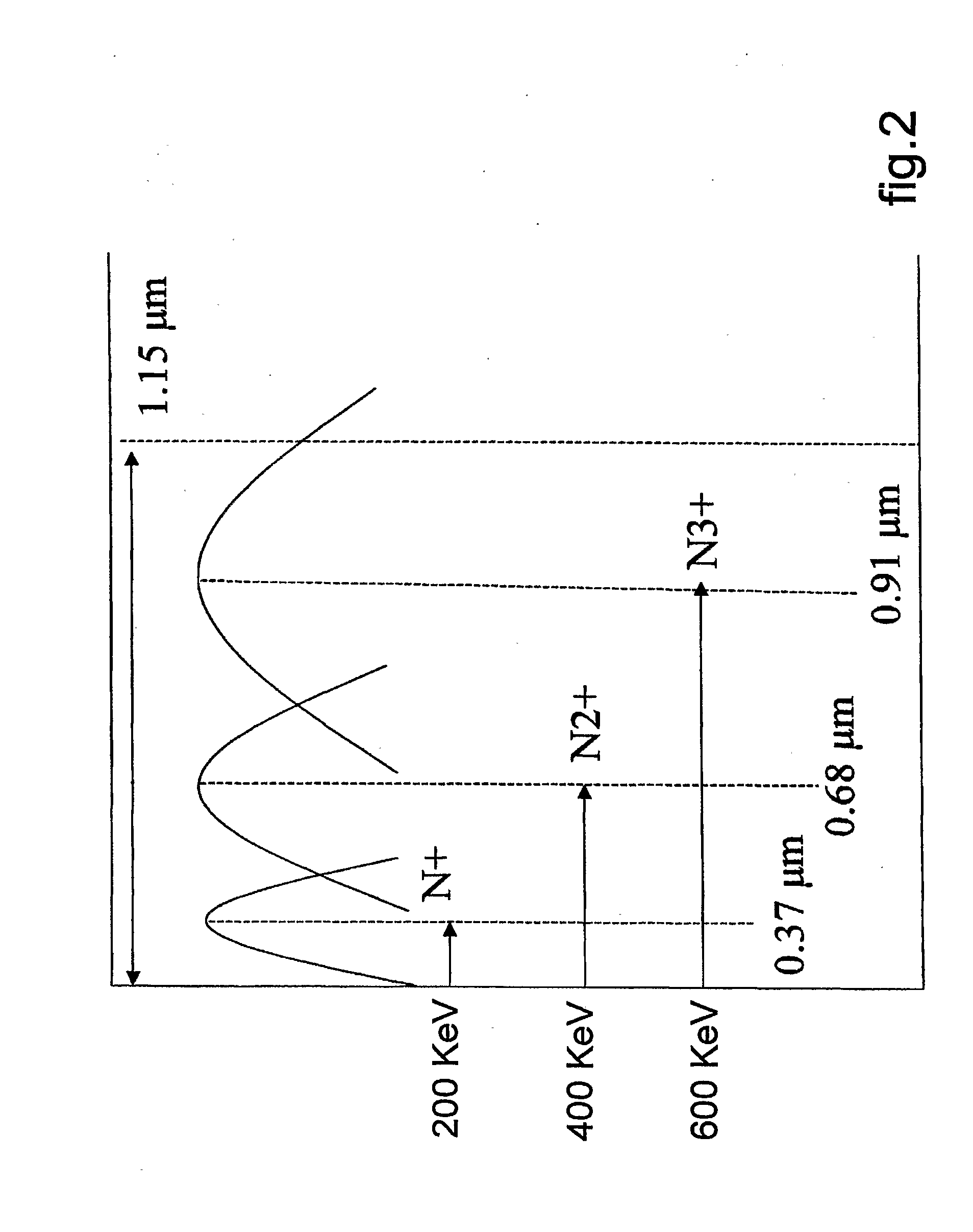
[0020]The present invention is further directed to such an apparatus that is operative to treat the aluminum alloy in depth, typically over a thickness on the order of 0 to 3 μm, and the use of which does not cause a change in the mechanical characteristics of the part to be treated, permitting its use after treatment without reworking of the part.
[0021]The present invention is also directed to such an apparatus operative to treat specific areas of the aluminum alloy part.
[0022]The present invention is also directed to such an apparatus that does not require long treatment times.
[0023]Finally, the present invention is directed to such an apparatus that is inexpensive so that it can be u...
PUM
| Property | Measurement | Unit |
|---|---|---|
| Temperature | aaaaa | aaaaa |
| Angle | aaaaa | aaaaa |
| Mass | aaaaa | aaaaa |
Abstract
Description
Claims
Application Information