Conductivity Counter

a technology of capacitance counter and sample cell, applied in the field of conductivity counter, can solve the problems of inaccuracy in measurement, lack of problems, and existence of two distinct capacitances of a typical fluid sample cell, and achieve the effect of eliminating the capacitances of the sample cell and enhancing the signal-to-noise ratio of the apparatus

Active Publication Date: 2009-08-27
BOARD OF SUPERVISORS OF LOUISIANA STATE UNIV & AGRI & MECHANICAL COLLEGE
View PDF7 Cites 25 Cited by
  • Summary
  • Abstract
  • Description
  • Claims
  • Application Information

AI Technical Summary

Benefits of technology

[0009]The present invention utilizes an equivalent parallel RLC circuit to effectively eliminate the capacitances of the sample cell. By operating such a circuit at its resonance frequency, the impedance of the reactive components (i.e., the capacitive and inductive components) cancel each other out, leaving only the purely resistive components. The resistance (or conductivity) remaining is due to the circuit components, the sample cell components, and the fluid sample. Once the circuit is operating at resonance frequency, the output signal caused by the background resistance components (i.e., those of the circuit, cell, and buffer solution) can be eliminated. The output signal is thus zeroed out prior to taking actual measurements, which allows use of a high-gain output amplifier, thus enhancing the signal to noise ratio of the apparatus.
[0010]In a preferred embodiment, the present invention has a variable frequency, high output impedance, current source; a sample cell having both resistive and capacitive characteristics electrically connected to the current source; a low-loss, low-noise inductance connected to the current source and in parallel with the sample cell, such that the sample cell and inductance effectively form a parallel RLC circuit; a high input impedance buffer amplifier connected to the output of the parallel RLC circuit; a phase sensitive detector connected to the output of the high input impedance buffer amplifier; a background conductivity offset circuit; a differencing amplifier with a first input connected to the output of the phase sensitive detector and a second input connected to the output of the background conductivity offset circuit; and, a high gain output amplifier connected to the output of the differencing amplifier.

Problems solved by technology

The problem identified and discussed in the article cited above is the existence of two distinct capacitances exhibited by a typical fluid sample cell.
Unfortunately, the existence of capacitance due to the cell itself leads to inaccuracies in the measurements.
Though the bipolar pulse method is reasonable fast, it is not without its share of problems.
This small sample tube size, however, does not work well with the bipolar pulse method because the two cell capacitances (Cd and Cp) are within less than one order of magnitude of each other.
Unless the opamp is in close proximity to the cell, the stray capacitance from the inverting input to ground can cause severe ringing in the bipolar pulse.
Finally, the experiments in micro-channels using this technique tend to have a low signal to noise ratio, and it is difficult to measure less than 2% changes in conductance.
The bipolar pulse method is one way to doing this, but it does not work well with small sample cells and small conductivity changes.

Method used


Image

  • Conductivity Counter
  • Conductivity Counter
  • Conductivity Counter

Examples


Embodiment Construction

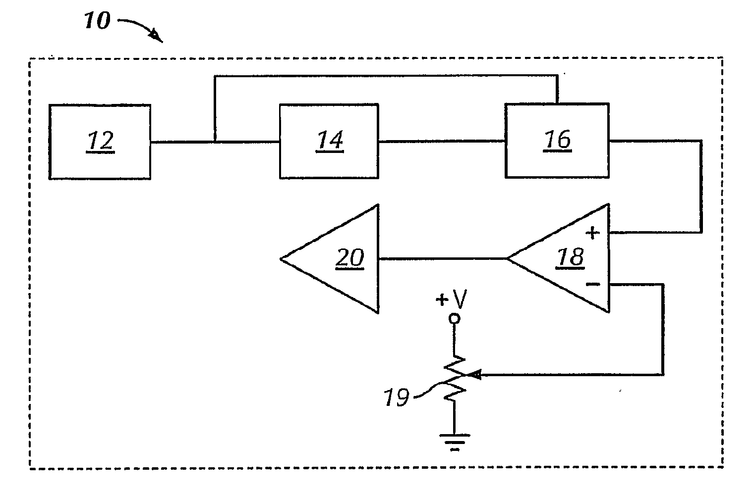
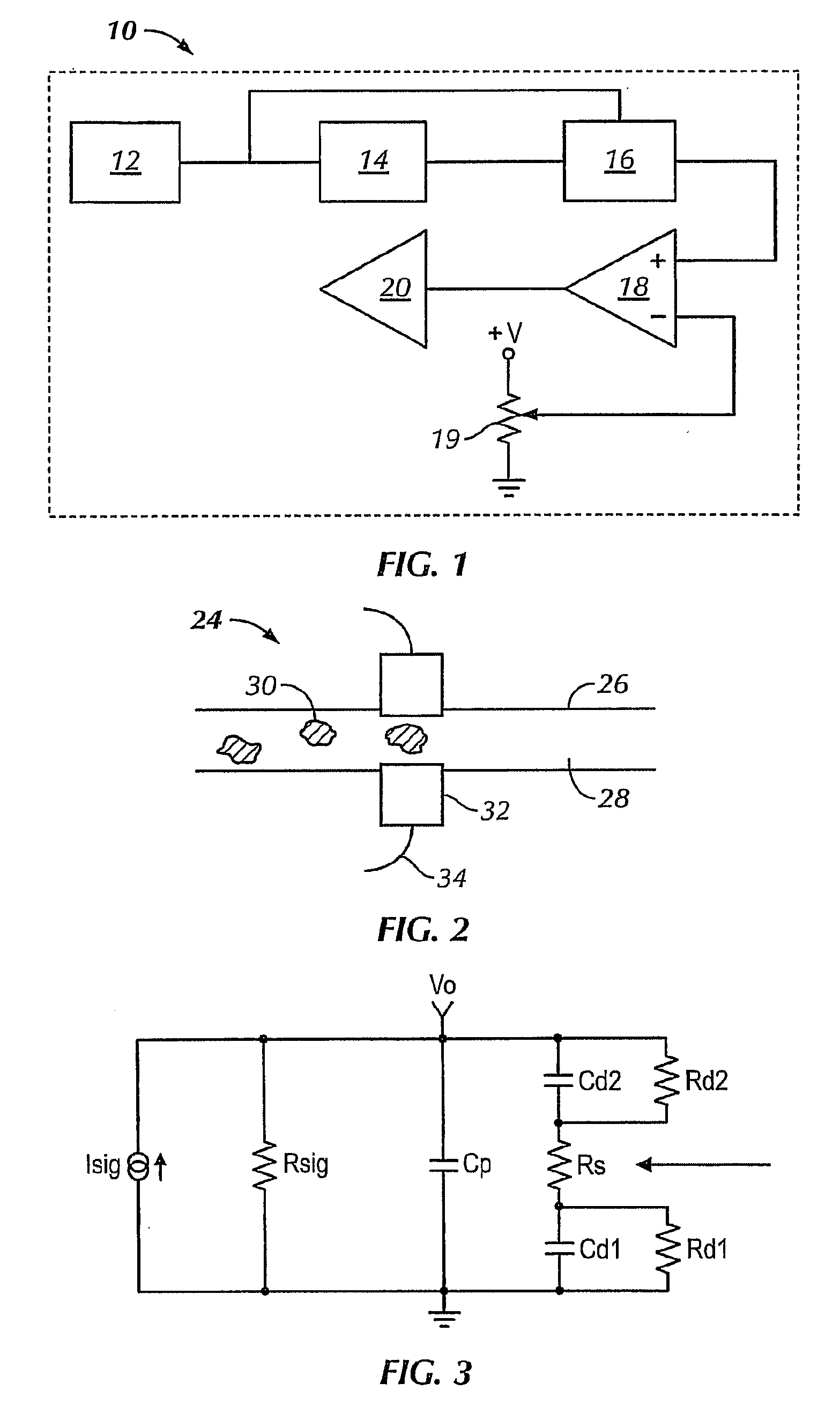
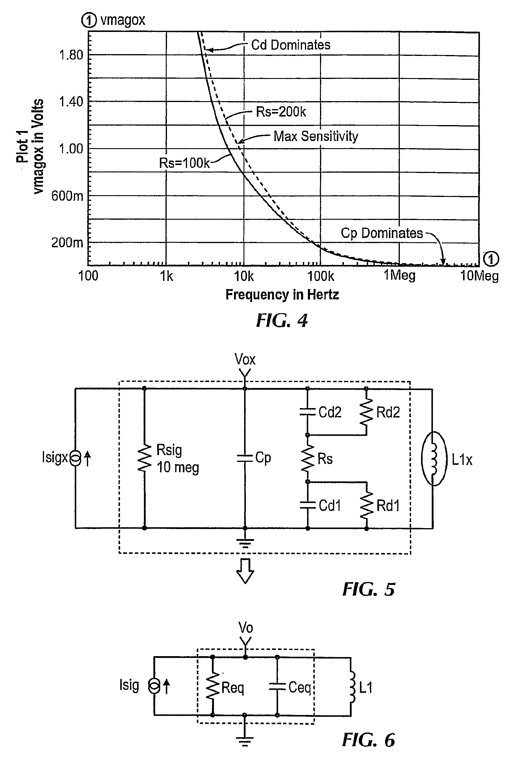
[0028]A conductivity counter apparatus 10 of the present invention is shown in block diagram form in FIG. 1. The first block represents a variable frequency, high output impedance current source 12, which supplies an excitation current to the sampling circuit 14. It is important that the sampling circuit 14 be effectively isolated from impedance effects of other parts of the circuit. For this reason, the excitation circuit should have high output impedance. The current source 12 is designed to provide this characteristic. It is also necessary that the current source 12 be tunable, that is, have a variable frequency that may be swept through a fairly broad range of frequencies. This capability is needed to find the resonance frequency of the equivalent RLC circuit, as described below.

[0029]The sampling circuit 14 is isolated from downstream impedance effects by using an output buffer amplifier having a high input impedance. This buffer is part of the sampling circuit block 14, as ill...


PUM

PropertyMeasurementUnit
lengthaaaaaaaaaa
diameteraaaaaaaaaa
resonance frequencyaaaaaaaaaa

Abstract

A conductivity counter and method of determining conductivity of a fluid sample are disclosed. The counter is suitable for high-speed, accurate counting of discrete events or items, such as cancer cells, passing through a fluid sample cell. A variable frequency current source is used to supply an excitation current to a sample cell connected in parallel with an inductance or the electrical equivalence of an inductance. This configuration can be accurately modeled as a parallel RLC circuit when the system is operated at a stable frequency. The current source frequency is tuned to the resonance frequency of the equivalent RLC circuit, which effectively eliminates the capacitive and inductive components of the impedance, leaving only purely resistive components. The output of the equivalent RLC circuit is connected to a high input impedance buffer amplifier and then to a phase sensitive detector, which detects the phase shift resulting from the equivalent RLC circuit. The output is filtered and a differencing amplifier is used to zero out the output signal due to the system components and the sample cell buffer solution prior to taking active readings. The remaining output signal is due to perturbations in the fluid sample, such as passing cancer cells. This output is sent to a high-gain output amplifier and then supplied to a suitable signal processing device or system, such as a computer.

Description

Priority Claim Under 35 U.S.C. 119(e)[0001]This application claims the benefit of U.S. Provisional Application No. 61 / 066,762, filed on Feb. 22, 2008.FIELD OF THE INVENTION [0002]The invention relates to an apparatus for making fast, accurate conductivity measurements of a fluid sample, and a method of calibrating a conductivity measurement apparatus and making conductivity measurements.BACKGROUND OF THE INVENTION [0003]Various techniques have been used to count events or items contained in fluid samples. Visual counting, using magnification and highly specialized recognition software, has been used. Conductivity counting also has been used to detect bands of DNA separated via electrophoresis. A bipolar pulse method has been used for such conductivity measurements. This method uses a bipolar pulse signal and makes use of the property that the sample cell parallel capacitance is orders of magnitude smaller than that of the series double-layer capacitance. This method is described in ...

Claims


Application Information

Patent Timeline
Patent Type & Authority Applications(United States)
IPC IPC(8): G01R27/08G01R35/00G01R27/28G01N27/02
CPCG01N15/1031G01N27/06G01R27/22G01N2015/1062
Inventor PATTERSON, DONALD A.
Owner BOARD OF SUPERVISORS OF LOUISIANA STATE UNIV & AGRI & MECHANICAL COLLEGE
Why Eureka
Try Eureka