Method and apparatus for coating powder material on substrate

a technology of powder material and substrate, applied in the direction of vacuum evaporation coating, coating, sputtering coating, etc., can solve the problems of difficult to coat predetermined materials on a deformation of the substrate made of polymer having low heat resistance, etc., to reduce the drag of powder, reduce the speed of spraying powder, and prevent the effect of powder deceleration

Inactive Publication Date: 2009-08-27
SEOUL NAT UNIV R&DB FOUND
View PDF7 Cites 9 Cited by
  • Summary
  • Abstract
  • Description
  • Claims
  • Application Information

AI Technical Summary

Benefits of technology

[0024]The vacuum state maintained in the chamber for the coating process makes better environments for deposition by reducing drag in powder, whereby deceleration of the powder being prevented. Furthermore, according as the grain size of powder is relatively smaller, and the velocity of spraying the powder is relatively faster, the powder is smoothly deposited on the substrate through the collision of powder particles against the substrate.
[0025]The small-sized powder particles minimize the deformation of substrate during their collision against the substrate. If a ceramic powder prepared under the aforementioned conditions is sprayed on the substrate, ceramic powder particles are deformed and recombined by the collision against the substrate so that the ceramic powder particles are properly coated on the substrate. As a result, various kinds of powder materials, such as metal or ceramic powder, can be coated on the substrate.

Problems solved by technology

However, the chemical vapor deposition (CVD) may cause limitations on application of various materials such a metal material since the chemical vapor deposition (CVD) uses the vapor-type material.
In addition, since the chemical vapor deposition (CVD) is performed under high temperature conditions, for example, 1000° C. or above, it is difficult to coat the predetermined material on a substrate made of polymer having low heat-resistance.
However, the thermal spray and gas deposition may have a problem such as deformation of the substrate made of polymer having low heat-resistance by a thermal impact because each of the thermal spray and gas deposition is performed at a high temperature of 600° C. or above.
The related art chemical vapor deposition, thermal spray and gas deposition have limitations on application of various materials to be coated on the substrate having low heat-resistance.
However, the related art cold spraying method has the following disadvantageous properties and limits of application.
However, since the cold spraying method requires the temperature of 300 to 600° C. in its coating process, it is difficult to coat the predetermined material on the substrate made of a material sensitive to heat through the use of cold spraying method.
Especially, in case of a display device using a flexible substrate which has attracted great attentions as a next-generation display device, the process temperature of 300 to 600° C. required in the cold spraying method is too high for the flexible substrate formed of organic polymer having low heat-resistance.
For the cold spraying method that requires the process temperature of 300 to 600° C., it is necessary to require the heating unit 30 and a complicated structure of pipe lines for carrying the gas therethrough, as shown in FIG. 1, thereby causing the cost increase.
Thus, there is a requirement for using the powder particle having the diameter above the predetermined value, thereby causing bad effects on the surface of substrate.
The cold spraying method can be applied only to the metal-powder coating process due to its process limitation.
Accordingly, it leads to limitation in selection of coating material.

Method used


Image

  • Method and apparatus for coating powder material on substrate
  • Method and apparatus for coating powder material on substrate
  • Method and apparatus for coating powder material on substrate

Examples


experimental example

[0070]The metal substrates made of stainless steel, copper, or aluminum alloy are prepared, and the polymer substrates made of polyethylene terephthalate (PET) and polymethyl methacrylate (PMMA) are prepared. Also, the ceramic powder made of TiO2 having a grain size less than about 5 μm (Sigma-Aldrich, St. Louis, Mo., USA) and Sn having a grain size less than about 5 μm (Sigma-Aldrich, St. Louis, Mo., USA) is prepared.

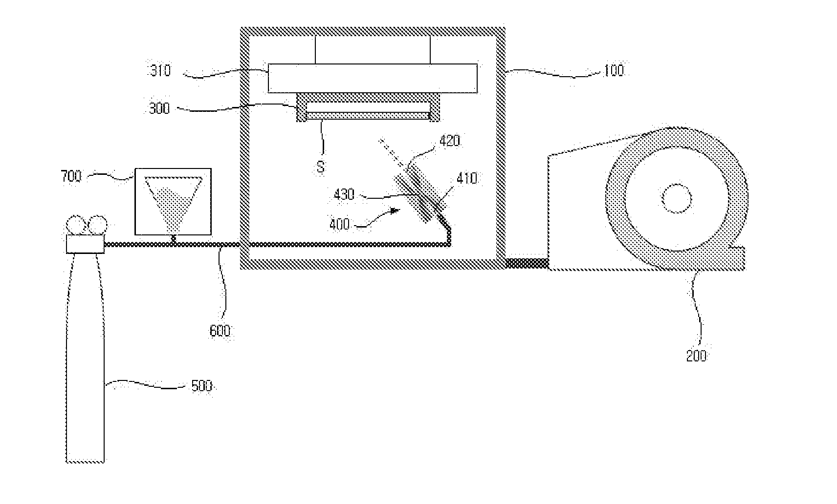
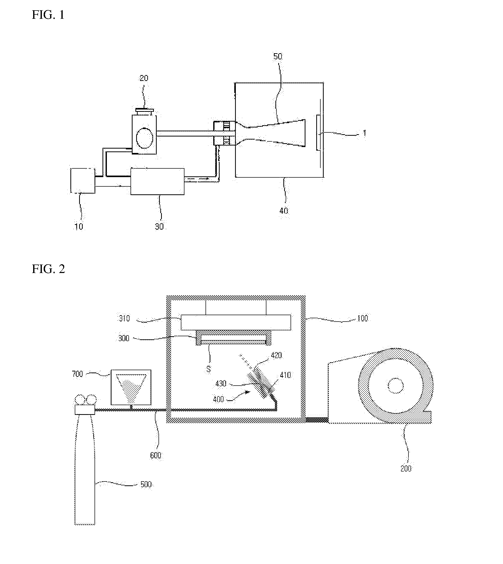
[0071]Under the conditions set as the following table 1, the ceramic powder or the metal power is deposited on 5×5 mm2 area of the substrate through the spray of compressed air.

TABLE 1ParametersValuesGas pressure(MPa)0.7Nozzle throat diameter(μm)590Spraying velocity(m / sec)600~800Chamber pressure(MPa)0.02~0.04Chamber temperature(° C.)15° C.Gas flow(L / min) 6~12Distance between substrate and nozzle(mm)1.5

[0072]At this time, the deposition results can be checked by optical images or scanning electron microscope (SEM) images, and the chemical composition of coating layer ca...


PUM

PropertyMeasurementUnit
velocityaaaaaaaaaa
grain sizeaaaaaaaaaa
velocityaaaaaaaaaa

Abstract

An apparatus and method for coating a powder material on a substrate is disclosed, to enable various materials such as metal or ceramic powder to be coated on a substrate made of a material having low heat-resistance, the method including supplying a predetermined powder; carrying the supplied powder to a predetermined spraying nozzle by injecting a gas at a room temperature; and spraying the powder carried under conditions of the room temperature and vacuum state on the substrate through spraying nozzle, wherein the grain size of predetermined powder is in a range between about 0.1 to about 10 μm, and the powder is sprayed on the substrate at a velocity of about 500 to about 1200 m/sec.

Description

FIELD[0001]The present invention generally relates to a method for coating various kinds of materials on a substrate, and more particularly to a method for coating various materials such as metal or ceramic on various substrates made of metal, ceramic or polymer under low temperature conditions.BACKGROUND[0002]The statements in this section merely provide background information related to the present disclosure and may not constitute prior art.[0003]There are many methods for coating a certain material on a substrate, for example, chemical vapor deposition (CVD), thermal spray, and gas deposition.[0004]The chemical vapor deposition (CVD), which is generally used in a semiconductor-fabrication process, can perform deposition of a predetermined material on a surface of substrate through a chemical reaction between the surface of substrate heated and a vapor-type material. However, the chemical vapor deposition (CVD) may cause limitations on application of various materials such a meta...

Claims


Application Information

Patent Timeline
Patent Type & Authority Applications(United States)
IPC IPC(8): B05D1/12C23C14/56
CPCC23C24/04B05B7/14
Inventor AHN, SUNG HOONCHUN, DOO MANKIM, MIN HYENGLEE, JAE CHUL
Owner SEOUL NAT UNIV R&DB FOUND
Why Eureka
Try Eureka