Method for manufacturing a stainless steel product

a three-dimensional steel and product technology, applied in the direction of solid-state diffusion coating, coating, metallic material coating process, etc., can solve the problem that semi-finished products cannot be subjected to machining, and achieve the effect of stabilising the microstructur

Active Publication Date: 2009-09-03
KONINKLIJKE PHILIPS ELECTRONICS NV
View PDF8 Cites 17 Cited by
  • Summary
  • Abstract
  • Description
  • Claims
  • Application Information

AI Technical Summary

Benefits of technology

[0014]Solution nitriding comprises a thermal treatment in a nitrogen-containing gas atmosphere at a temperature of between 1000° C. and 1200° C. The temperature, pressure and duration of the nitrogen enrichment are selected in such a way that a nitrogen saturation throughout the thickness of the shaped product is obtained, with the nitrogen content being between a lower limit of 0.3% by weight and an upper limit that is provided by the beginning of nitride separation during the nitrogen enrichment. A suitable partial nitrogen pressure to carry out the thermal treatment is between 0.01 and 0.3 MPa, preferably, at about 0.1 MPa.
[0015]The subsequent cooling is effected at such a rate and nitrogen pressure that nitride separation is avoided. This can e.g. be realized by recirculation gas quenching under a nitrogen pressure set in a range between at least the partial nitrogen pressure at which the thermal treatment is carried out and 2 MPa, at a cooling rate of at least 5° C./sec until a temperature of 20° C. is reached.
[0016]Optionally, the shaped product may be tempered to release built in stresses and to stabilise the microstructure at the tempering temperature. Preferably tempering is carried out by subjecting the finished product at a temperature of between 650° C. and 100° C., preferab

Problems solved by technology

Due to the fact that nitrogen enrichment in U.S. Pat. No. 5,503,687 is limited to a surface layer the semi finished products cannot be s

Method used


Image

  • Method for manufacturing a stainless steel product
  • Method for manufacturing a stainless steel product

Examples


Embodiment Construction

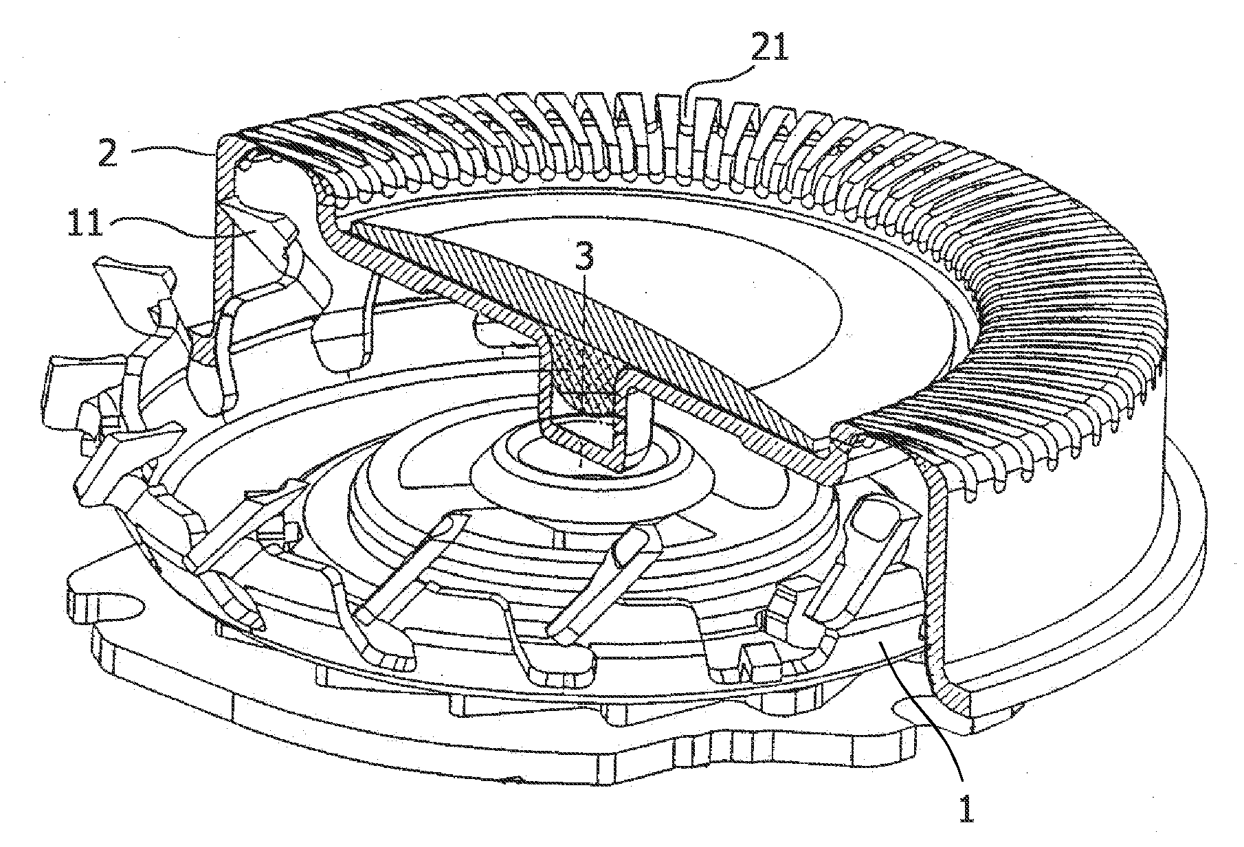
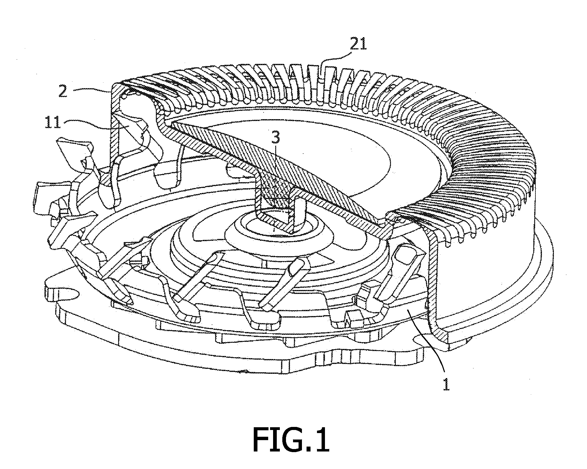
[0023]The assembly of the rotary shaving assembly in FIG. 1 consists of a rotary cutter 1 and a shear plate 2. The rotary cutter comprises a cutter disc along which periphery cutter blades are offset from the plane of the disc. The blades are arranged in an annular configuration along the periphery, symmetrical relative to a central axis 3.

[0024]The shear plate 2 was stamped from a sheet of martensitic stainless steel (X32Cr14) with a thickness of 400 μm. The thus formed three dimensional semi finished cup was solution nitrided at 1100° C. subsequently during 14 minutes at a nitrogen pressure of 0.093 MPA and 28 minutes at a nitrogen pressure of 0.043 MPa, until saturation throughout the thickness with nitrogen was reached. Recirculation gas quenching was applied under 1 MPa nitrogen gas pressure, during which cooling between 1100° C. and about 450° C. is carried out at a speed of about 25° C. / sec. Tempering was done at 170° C. for 60 minutes under a nitrogen pressure of 0.2 MPa. Su...


PUM

PropertyMeasurementUnit
Temperatureaaaaaaaaaa

Abstract

The invention relates to a method for making a thin finished product to be formed by deformation that combines strength with resistance to a highly corrosive environment. The method comprises forming a sheet of stainless steel with a microstructure consisting predominantly of ferrite, austenite, martensite or a mixture thereof, with a thickness of less than 3 mm, to a three dimensional semi finished product, treating said semi finished product with a nitrogen-containing atmosphere at a temperature of between 1000° C. and 1200° C. during a time and under a nitrogen pressure, sufficient to saturate the product through the thickness with a nitrogen content between a lower limit of 0.3 wt % and an upper limit that is provided by the beginning of nitride separation, cooling down said product at such a rate and nitrogen pressure that nitride separation is avoided, and subsequently machining the nitrogen saturated semi- finished product to the finished product. The invention further relates to a rotary shaving assembly prepared by the method of the invention.

Description

FIELD OF THE INVENTION[0001]The invention relates to a method for the manufacturing of a thin three dimensional steel product by deformation. A thin three dimensional product is understood to be a product having an envelope, whose dimensions in three perpendicular directions exceed a largest thickness of the product, this largest thickness being less than 3 mm, preferably less than 1 mm. Deformation for example can include methods like deep drawing or stamping.[0002]Examples of these thin three dimensional products are a rotary cutter and shear plate of a cutting assembly of an electric rotary-shaver apparatus. Some recent models of rotary-shavers are used with shaving cream and can be rinsed with running water. This requires a steel type for the cutting assembly that not only combines strength with formability, but that should also resist a highly corrosive environment.[0003]The invention further relates to a thin three dimensional product that is resistant against such a highly co...

Claims


Application Information

Patent Timeline
IPC IPC(8): C23C8/26C22C38/00
CPCC23C8/26C21D6/002C23C8/80
Inventor BLAAUW, HUBERT SJOERDHOMMES, MARTINVINKENVLEUGEL, LUCIUS THEODORUS
Owner KONINKLIJKE PHILIPS ELECTRONICS NV
Why Eureka
Try Eureka