Method for Evaluating A Measured Parameter

a measurement parameter and measurement method technology, applied in the field of measurement parameter evaluation, can solve the problems of reducing the attainable measurement accuracy, and disadvantageous effect on the attainable accuracy, so as to achieve high simplification of the entire signal processing and achieve more accurate results, the effect of high vacuum pressure acquisition

Active Publication Date: 2009-09-03
INFICON HLDG AG
View PDF7 Cites 20 Cited by
  • Summary
  • Abstract
  • Description
  • Claims
  • Application Information

AI Technical Summary

Benefits of technology

[0024]According to the present invention it is consequently possible to determine with a calculation function in a computing unit from the spectrum directly, without circuitous routes, the interferogram which contains as the output signal directly the unit of length which corresponds to the optical path length difference and consequently to the parameter to be measured. The calculation function preferably contains, at least in a first approximation, a cosine function. The cosine function surprisingly makes possible the high simplification of the entire signal processing and of the measuring arrangement. It is understood, that by this are also understood purely trigonometrically transformed representations of a cosine function, which are subsequently represented, for example, with the other angle functions, such as sine, tangent, cotangent functions or corresponding approximations.
[0025]It is also possible that the coupling-out of at least a portion of the light reflected from the cavity takes place with at least one further or several optical waveguides which are disposed separately next to the feeding optical waveguide. Alternatively, several optical waveguides can also be utilized for coupling the light into the cavity and for coupling out the light reflected from the cavity, which, for example, are disposed jointly in a mixed bundle of fibers leading to and away. In every case, however, the reflected light is conducted to an optical spectrometer. The embodiment with only one optical waveg

Problems solved by technology

Such a wedge with the necessary layers, respectively polarizers, is complex and therefore expensive in production and has undesirable dispersion effects which affect the resulting interferogram and reduce the attainable measuring accuracy.
This dependence can be (partially) compensated, yet has nevertheless a disadvantageous effect on the attainable accuracy and entails increased complexity and expenditures for the realization.
In practice this can only be achieved under high complexity and expenditure with corresponding optically effective coatings.
However, such are not realizable in every case and one is forced to utilize non-coated glass surfaces as mirrors or partially transmissive mirrors.
In such a case a measurement signal is obtained with very poor contrast or a very low signal-to-noise ratio.
In this case for the evaluation of the measuring signal very high expenditures must be spent and the attainable accuracy is limited.
A significant disadvantage of this arrangement proposed here, is the complicated calculation of the measured value via n

Method used


Image

  • Method for Evaluating A Measured Parameter
  • Method for Evaluating A Measured Parameter
  • Method for Evaluating A Measured Parameter

Examples


Embodiment Construction

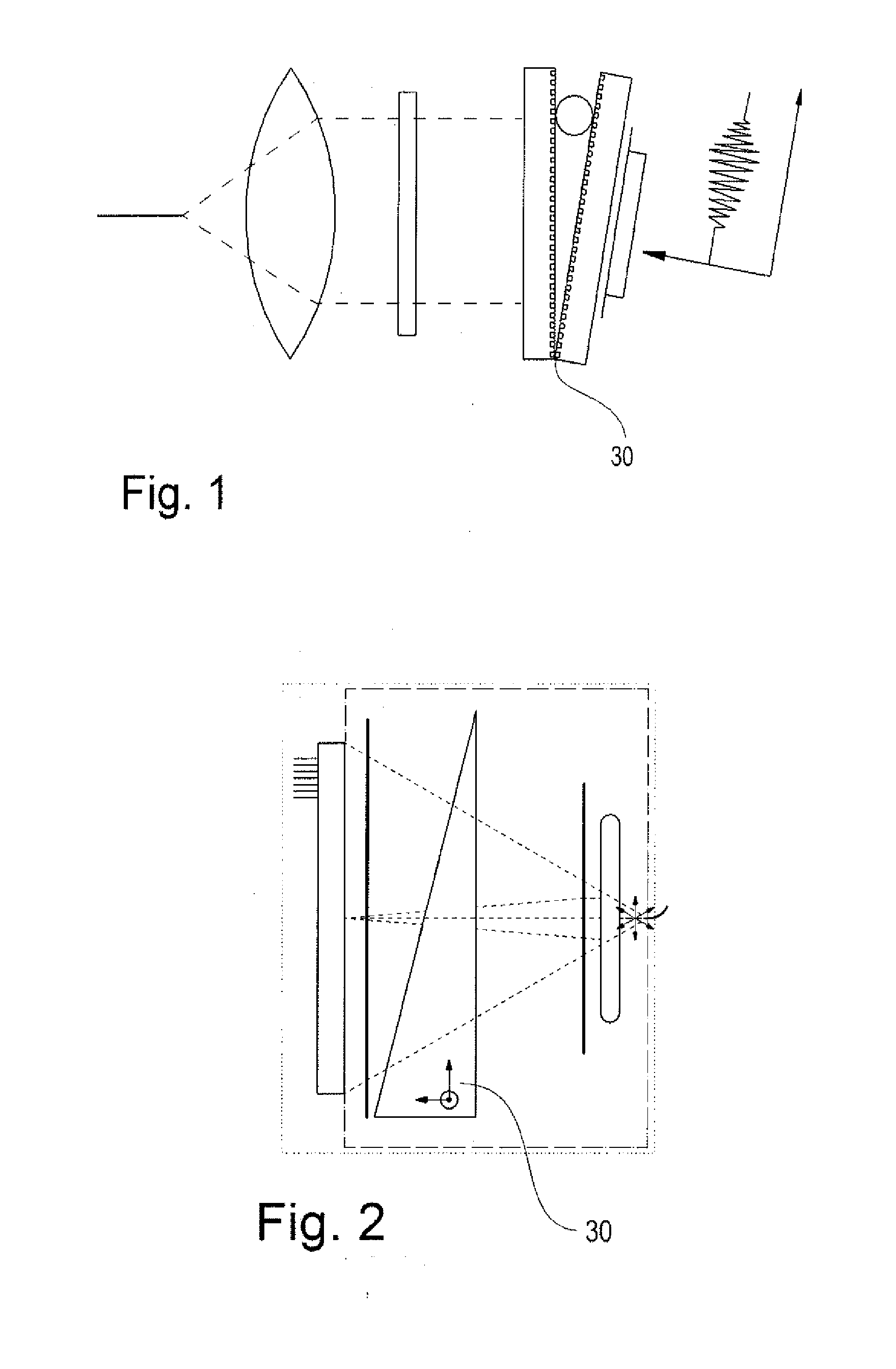
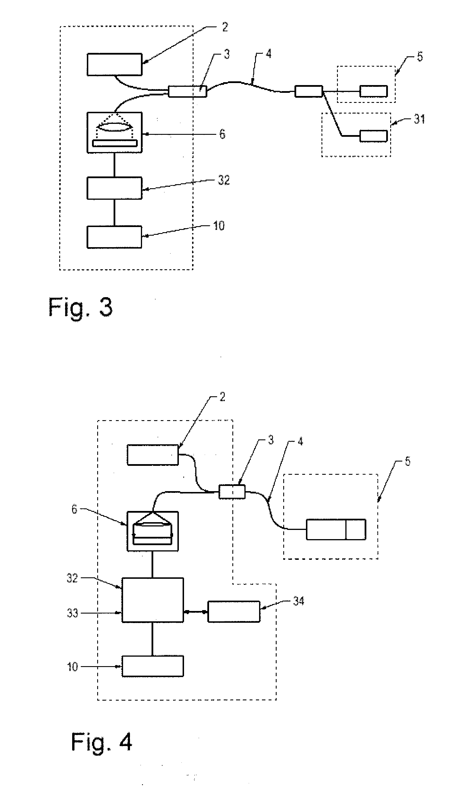
[0040]FIGS. 1 to 4 depict schematically known measuring systems based on optical interference principles, which systems have already been described in the introduction.

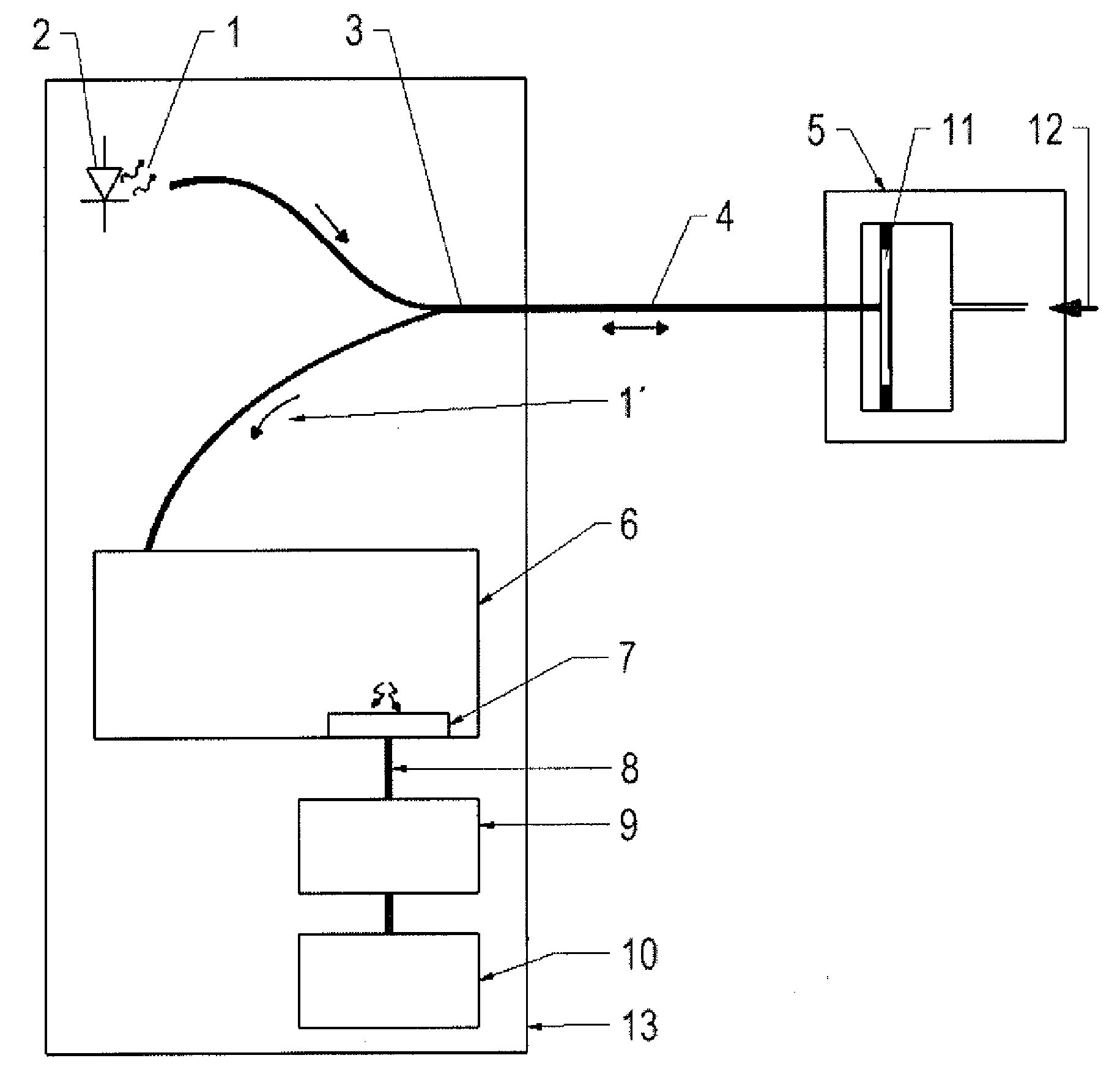
[0041]FIG. 5 depicts a typical structure of a preferred diaphragm-based Fabry-Perot measuring system. The system is comprised of an evaluation unit 13 and a sensor 5 which are connected by means of optical waveguide 4 with the evaluation unit 13. Light 1 from a white light source 2 is conducted via a coupler 3 and optical waveguide 4 to the measuring sensor 5 developed as a Fabry-Perot sensor 5 with a cavity 11, and is modulated in such a cavity as a function of the parameter to be measured. The modulated light is conducted via the same optical waveguide 4 and coupler 3 to an optical spectrometer 6. This spectrometer 6 generates an output signal, the spectrometer signal 8, by measuring overall m0 intensity values sλ(λm) at the different wavelengths λm. Each value sλ(λm) corresponds to the measured intensity at the wav...


PUM


Abstract

For evaluation of a measured parameter with a measuring cell having a cavity which generates for light an optical path length difference changing corresponding to the variation of the measured parameter, the method includes: introducing light from a white light source with the aid of an optical waveguide via a coupler (3) disposed in the path of the optical waveguide into the cavity, coupling out at least a portion of the light reflected back into the optical waveguide from the cavity with the aid of the coupler and conducting this reflected light to an optical spectrometer, determining the optical spectrum of the reflected light in the spectrometer and generating a spectrometer signal, conducting the spectrometer signal to a computing unit, wherein the spectrometer signal is directly converted through the computing unit to an interferogram and from its intensity progression the location of the particular extremal amplitude value is determined and this particular location represents directly the particular value of the optical path length difference in the cavity, which comprises the measured parameter.

Description

FIELD AND BACKGROUND OF THE INVENTION [0001]The invention relates to a method for evaluating a measured parameter with a measuring cell, as well as to a measuring arrangement.[0002]The invention relates to an evaluating method in connection with a fiber optic interferometric sensor measuring system for measuring measured parameters such as pressure, temperature, expansion and optical refractive indices. In particular, the simple and precise acquisition of vacuum pressures should be possible.[0003]With measuring systems based on principles of interference, various measured parameters can be measured with high resolution and accuracy. Typical representatives of such measuring systems are such which are based on Fabry-Perot (FP) sensors. These measure the optical path length difference in the so-called Fabry-Perot sensor cavity. This path length difference changes as a function of the physical parameter to be measured and corresponds to the magnitude of the difference of the optical pa...

Claims


Application Information

Patent Timeline
IPC IPC(8): G01B9/02
CPCG01B9/02G01L9/0079G01K11/3206G01B9/02044G01B9/0209G01B2290/25
Inventor WAEGLI, PETERMULLIS, FELIX
Owner INFICON HLDG AG
Why Eureka
Try Eureka