Control apparatus for internal combustion engine having motor-driven supercharger

a technology of control apparatus and internal combustion engine, which is applied in the direction of electric control, machines/engines, instruments, etc., can solve the problems of exhaust emission and fuel efficiency deterioration

Inactive Publication Date: 2009-09-03
TOYOTA JIDOSHA KK
View PDF7 Cites 25 Cited by
  • Summary
  • Abstract
  • Description
  • Claims
  • Application Information

AI Technical Summary

Benefits of technology

[0025]According to the ninth aspect of the present invention, when the electric motor is going to be run to raise the rotation speed of the supercharger before torque buildup becomes actually required, the bypass valve is opened before running the electric motor. This can reduce the difference between the intake air flow measured from the signal of the intake air flow sensor and the air flow inhaled actually into the internal combustion engine since compression of intake air by the supercharger is suppressed. It is therefore possible to control the internal combustion engine based on the accurate air flow inhaled into the engine even during the execution of air-bypass.

Problems solved by technology

If the signal of the intake air flow sensor does not accurately represent the actual air flow inhaled into the internal combustion engine, the exhaust emission and fuel efficiency may deteriorate since it is not possible to accurately perform fuel injection amount control and other engine controls.

Method used


Image

  • Control apparatus for internal combustion engine having motor-driven supercharger
  • Control apparatus for internal combustion engine having motor-driven supercharger
  • Control apparatus for internal combustion engine having motor-driven supercharger

Examples


first embodiment

[0034]The following will describe a first embodiment of the present invention with reference to FIGS. 1 through 5.

[Description of Engine System Configuration]

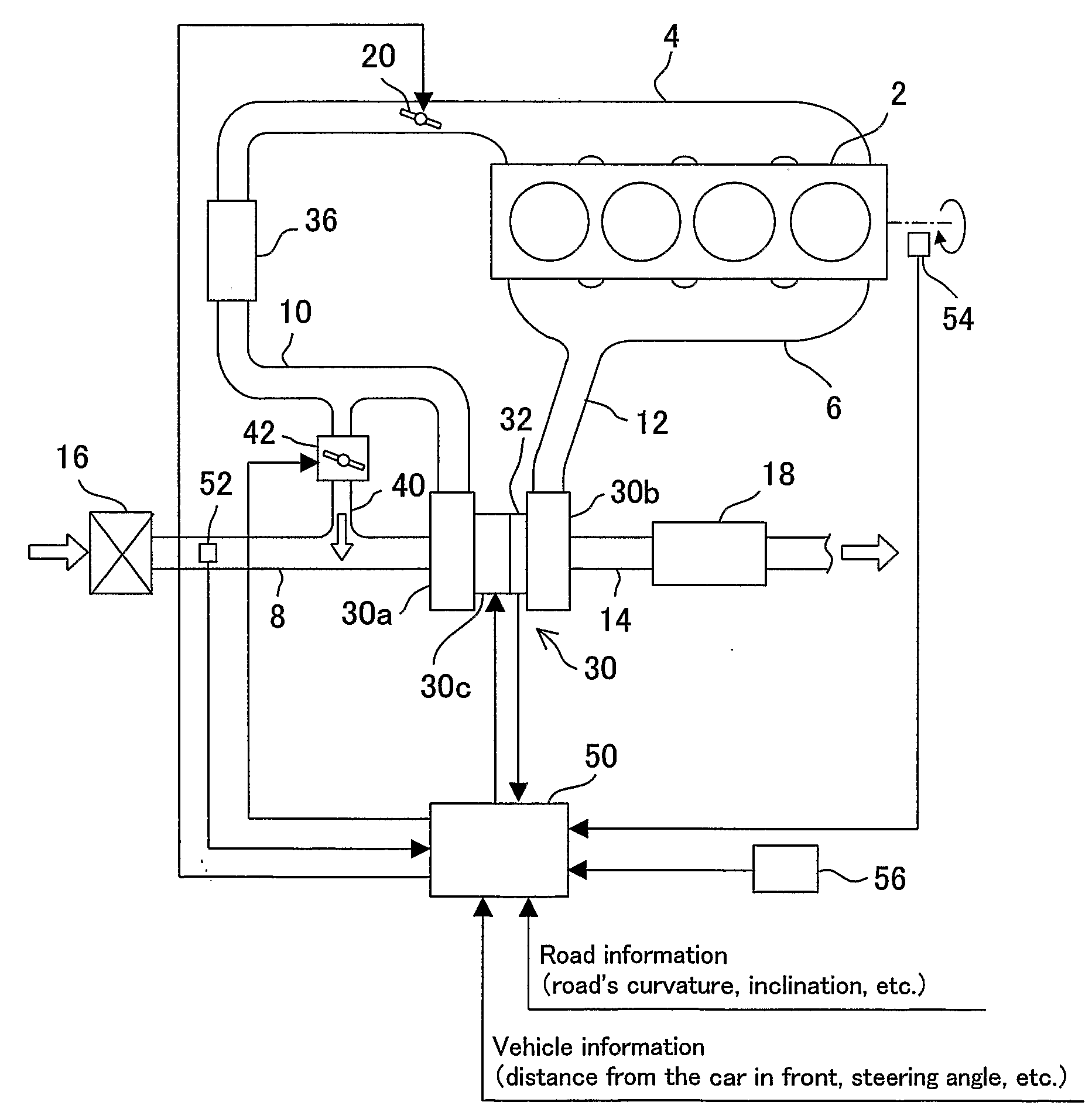
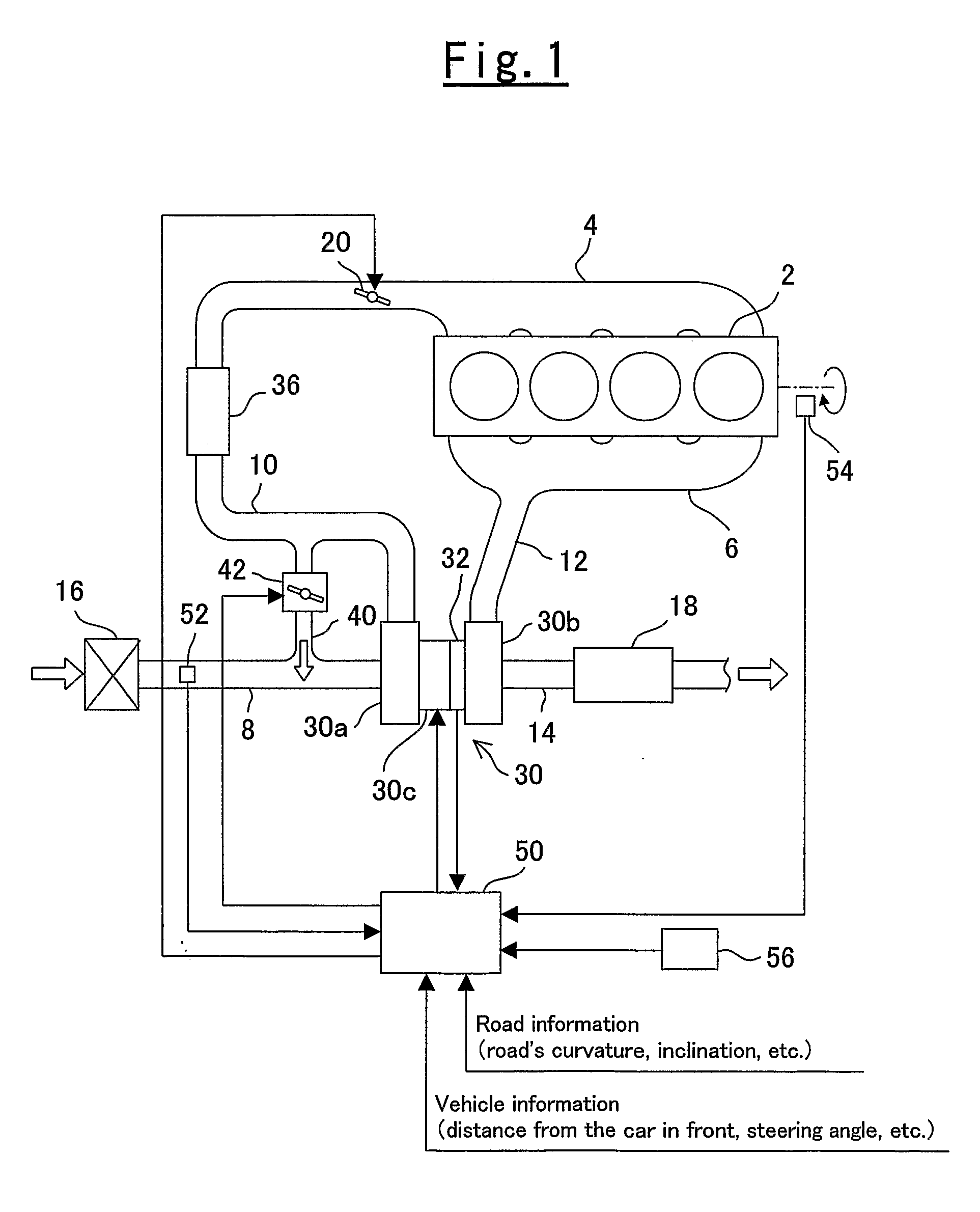
[0035]FIG. 1 schematically shows the configuration of an internal combustion engine having a motor-driven supercharger to which a control apparatus, the first embodiment of the present invention, is applied. In the present embodiment, the present invention is applied to a gasoline engine (hereinafter, denoted simply as the engine). This engine comprises an engine body 2 which has a plurality of cylinders (four cylinders in FIG. 1). To the engine body 2, an intake manifold 4 to distribute air the respective cylinders and an exhaust manifold 6 to gather exhaust gas from the respective cylinders.

[0036]This engine is provided with a motor-driven turbocharger (motor assist turbocharger, hereinafter denoted as the MAT) 30. The MAT 30 comprises of a compressor 30a, a turbine 30b and an electric motor 30c disposed between the compresso...

second embodiment

[0076]The following describes a second embodiment of the present invention with reference to FIG. 6.

[0077]A control apparatus for an internal combustion engine having a motor-driven supercharger, according to the present embodiment, is also implemented in the same configuration as FIG. 1. In the present embodiment, however, the control apparatus is implemented by making the ECU 50 execute a routine shown in FIG. 6 instead of the routine shown in FIG. 3.

[Description of Pre-assist Control]

[0078]The present control apparatus embodiment is different in terms of pre-assist control processing from the first control apparatus embodiment. FIG. 6 provides a flowchart showing a pre-assist control routine which is executed by the ECU 50. Each step of processing in the routine of FIG. 6 is given the same step number as the corresponding step, if any, in the routine of FIG. 3 if there is no difference in terms of processing. In addition, description of processing is omitted unless not already de...

third embodiment

[0083]The following describes a third embodiment of the present invention with reference to FIGS. 7 and 8.

[Description of Engine System Configuration]

[0084]FIG. 7 schematically shows the configuration of an internal combustion engine having a motor-driven supercharger where a third control apparatus embodiment of the present invention is applied. Each component in FIG. 7 is given the same reference numeral as the corresponding one, if any, shown in FIG. 1. In addition, configurational description is omitted unless not already described.

[0085]The engine according to the present embodiment is different from the engine according to the first embodiment in that an EGR is included. As shown in FIG. 7, an EGR passage 22 is connected to the intake passage 10 between the throttle valve 20 and the intake manifold 4. The opposite end of the EGR passage 22 is connected to the exhaust manifold 6. The EGR passage 22 is provided with an EGR cooler 26 to cool the EGR gas which flows therein. Downs...


PUM


Abstract

The air flow inhaled into the internal combustion engine is calculated based on the operation state of the electric motor, the operational state of the bypass valve and the signal of the intake air flow sensor. Immediately after the bypass valve is opened when the electric motor is running, the air flow inhaled into the internal combustion engine may be calculated by acquiring the bypass air flow through the bypass passage and using the acquired bypass air flow to correct the intake air flow measured from the signal of the intake air flow sensor. Based on the calculated air flow inhaled into the internal combustion engine, control parameters which concern the output power of the internal combustion engine are adjusted.

Description

TECHNICAL FIELD[0001]The present invention relates to a control apparatus for an internal combustion engine having a motor-driven supercharger. In particulars the invention relates to a control apparatus for an internal combustion engine having a motor-driven supercharger wherein the compressor can be bypassed through a bypass passage between the downstream and upstream of the supercharger's compressor.BACKGROUND ART[0002]Setting a motor to the rotation axis of a turbocharger is known in conventional art. Such a motor-driven turbocharger is driven to assist the rotation of the compressor. It is therefore possible to attain a necessary level of boost pressure when necessary regardless of whether the exhaust energy supplied from the internals combustion engine is large or small. Thus, the motor-driven turbocharger can realize high boost pressure by forcibly driving the compressor even when the engine rotation speed is low, that is, when the exhaust gas flow to drive the turbine is low...

Claims


Application Information

Patent Timeline
Patent Type & Authority Applications(United States)
IPC IPC(8): F02D41/00F02D41/18F02B37/12
CPCF02B29/0406F02B37/16F02D41/0007Y02T10/144F02D41/18F02M25/0707F02M25/0727F02D41/0065F02M26/05F02M26/23Y02T10/12
Inventor IGARASHI, OSAMU
Owner TOYOTA JIDOSHA KK
Why Eureka
Try Eureka