Extreme ultra violet light source apparatus

a light source and ultra violet technology, applied in the field of extreme ultra violet (euv) light source apparatus, can solve the problems of affecting the operation deteriorating the functions so as to reduce the operation cost of the euv light source apparatus

Active Publication Date: 2009-09-10
GIGAPHOTON
View PDF4 Cites 32 Cited by
  • Summary
  • Abstract
  • Description
  • Claims
  • Application Information

AI Technical Summary

Benefits of technology

[0012]The present invention has been achieved in view of the above-mentioned problems. A purpose of the present invention is to provide an extreme ultra violet light source apparatus in which debris staying and accumulating within a chamber can be prevented from contaminating the chamber, deteriorating the performance of important optical component such as a collector mirror, and deteriorating the performance of a vacuum intake and exhausting unit, and extreme ultra violet light can stably be generated in a long period.
[0015]According to the present invention, by catching the debris within the chamber in the exhaust path and collecting the caught debris out of the chamber without stopping the generation of EUV light, the inserted target material can be collected or removed, the intervals of cleaning operation within the chamber while releasing the vacuum can be greatly increased, the EUV light source apparatus can be continuously operated at a practical level, and the target material can be effectively utilized so that the operation cost of the EUV light source apparatus can be reduced.

Problems solved by technology

In the LPP EUV light source apparatus, when plasma is generated by applying a laser beam to a target, especially, if debris containing fast ions, neutral particles, and residual droplets emitted from the plasma are left, the operation of the EUV light source apparatus is disturbed.
Further, regarding the other structures, their functions are deteriorated and the operation as the EUV light source is hindered due to shape changes.
Furthermore, the neutral particles and the residual droplets of the target are deposited on the structures including the collector mirror within the chamber and decrease the function of the EUV light source apparatus.
For example, in a turbo-molecular pump for maintaining the degree of vacuum within the chamber, if the neutral particles and the residual droplets are deposited on turbine blades, the exhaust velocity becomes lower and, in the worst case, the blades collide with each other and are damaged, the turbo-molecular pump breaks down, and the EUV light source apparatus no longer operates.
Accordingly, even if the debris can be prevented from reaching the main optical components such as a collector mirror, the LPP EUV light source apparatus cannot stably be run in a long period.
That is, in the EUV light source apparatus, the debris, which are produced from the plasma when a laser beam is applied to a target to generate the plasma for EUV light generation, stay and gradually accumulate within the chamber, and the accumulated debris contaminate the interior of the chamber.
Accordingly, there are problems that the accumulated debris are deposited on the main optical components, and thereby, reduce the reflectance or transmittance of the main optical components and deteriorate the performance of the main optical components, and the laser beam and EUV light are scattered due to increase of debris gradually staying within the chamber and efficient EUV light generation and collection are inhibited.
Further, there is a problem that the staying debris enter the pump attached for evacuating the chamber and deteriorate the evacuation performance of the pump, and the operation time of the apparatus becomes shorter for maintenance of the pump.
In any case, the long-term operation stability of the LPP EUV light source apparatus is deteriorated by the debris dispersing and staying within the chamber for a long period, and resolving these problems have been an issue.

Method used


Image

  • Extreme ultra violet light source apparatus
  • Extreme ultra violet light source apparatus
  • Extreme ultra violet light source apparatus

Examples


first embodiment

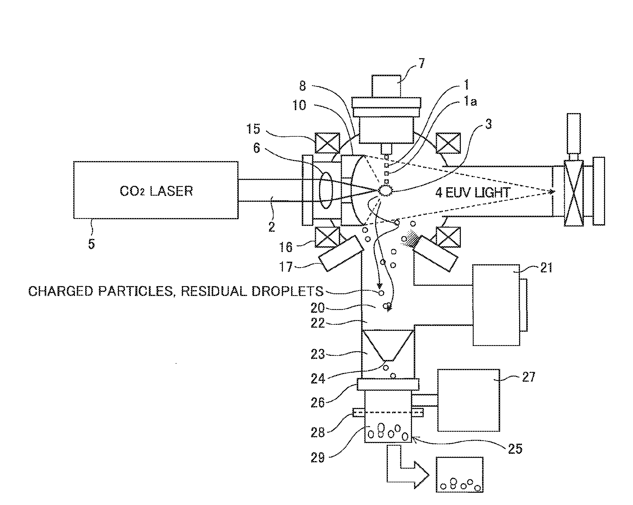
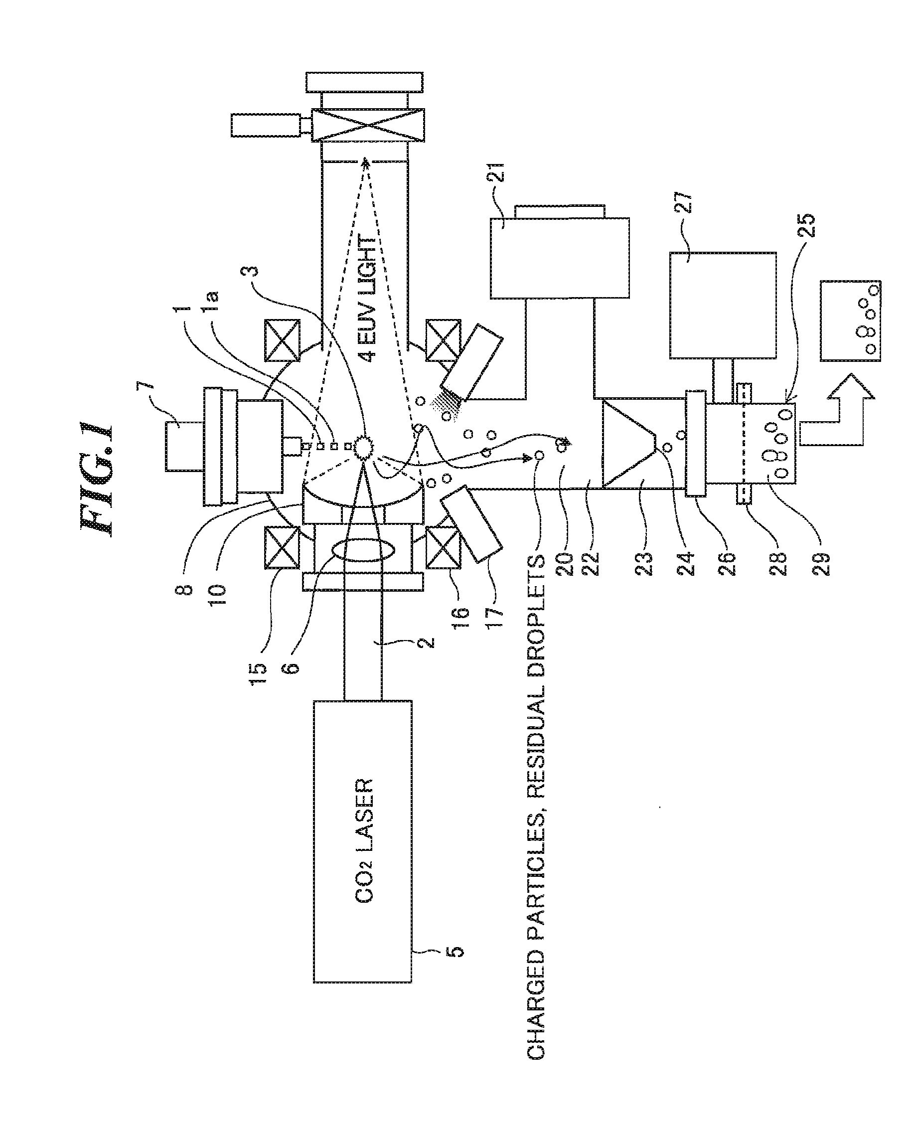
[0027]FIG. 1 is a diagram for explanation of the present invention. Referring to FIG. 1, a basic configuration and an operation of an EUV light source apparatus according to the embodiment will be explained. The EUV light source apparatus shown in FIG. 1 employs a laser produced plasma (LPP) system for generating EUV light by applying a laser beam to a target material for excitation.

[0028]As shown in FIG. 1, the EUV light source apparatus includes a chamber 8 in which EUV light is generated, a target supply unit 7 for supplying a target 1 to a predetermined position within the chamber 8, a driver laser 5 for generating an excitation laser beam 2 to be applied to the target 1, a laser beam focusing optics 6 for collecting the excitation laser beam 2 generated by the driver laser 5, and a collector mirror 10 for collecting EUV light 4 emitted from plasma 3 generated when the excitation laser beam 2 is applied to the target 1 and outputting the EUV light 4.

[0029]In the EUV light source...

second embodiment

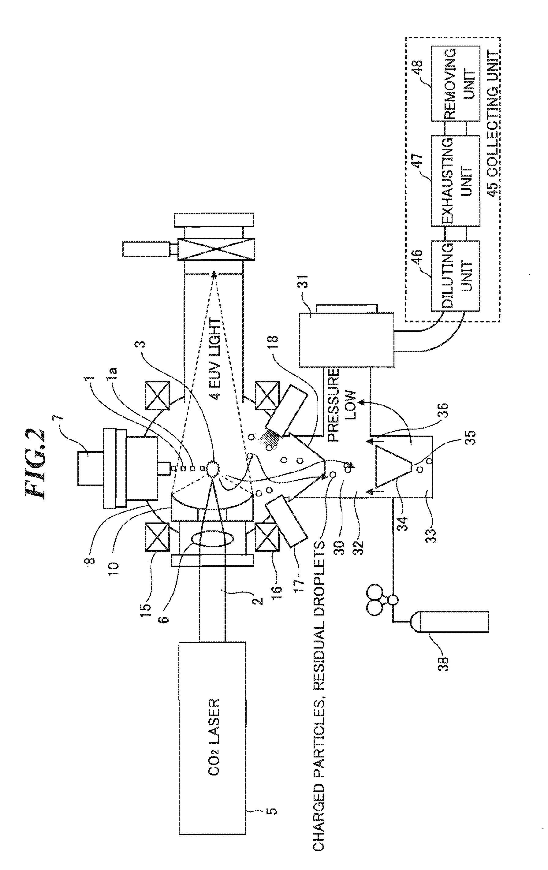
[0050]In the present invention, since the debris are allowed to react with the reactive gas and collected as the reaction product gas, the degree of freedom of choice regarding the transportation and treatment of the gasified debris is great. For example, the collecting operation can be performed even when the units 46, 47 at the downstream of the diluting unit 46 are provided outside of a clean room where the EUV light source apparatus is installed. Thereby, the clean room can be prevented from contaminating by the collected debris.

[0051]Next, referring to FIG. 4, the third embodiment of the present invention will be explained. The third embodiment of the present invention is the same as the second embodiment of the present invention shown in FIG. 2 in the configuration to the exhaust chamber 32, and FIG. 4 only shows the skimmer 18 and the downstream side of the third embodiment of the present invention, which differ from those of the second embodiment of the present invention. In...

third embodiment

[0052]As explained above, in the present invention, the amount of the reactive gas and the reaction product gas exhausted by the debris exhaust TMP 51 can be reduced. Since the amount of exhausted gas by the debris exhaust TMP 51 is reduced, the lower capacity of the debris exhaust TMP 51 can be available and the cost can be reduced. Although the total number of exhausting units is increased, the price of a typical pump is a fraction of the price of the TMP, and the effect of the reduced cost due to the lower capacity of the debris exhaust TMP 51 is great.

[0053]Next, referring to FIG. 5, the fourth embodiment of the present invention will be explained. The fourth embodiment of the present invention has a similar configuration to that of the second embodiment of the present invention, however, a heating unit 65 is provided in a catching and reaction chamber 63. That is, by heating the catching and reaction chamber 63, the reaction time taken for reaction of the debris and the reactiv...


PUM


Abstract

An extreme ultra violet light source apparatus in which debris staying and accumulating within a chamber can be prevented from contaminating the chamber and deteriorating the performance of important optical component. The extreme ultra violet light source apparatus includes: a chamber in which extreme ultra violet light is generated; a driver laser for applying a laser beam to a target supplied to a predetermined position within the chamber to generate plasma; a collector mirror provided within the chamber, for collecting and outputting the extreme ultra violet light radiated from the plasma; an exhaust path communicating with the chamber and connected to an exhausting device, for maintaining an interior of the chamber at a certain pressure; a catching chamber provided in the exhaust path, for catching debris generated from the plasma; and a collecting unit for collecting the caught debris out of the chamber.

Description

BACKGROUND OF THE INVENTION[0001]1. Field of the Invention[0002]The present invention relates to an extreme ultra violet (EUV) light source apparatus to be used as a light source of exposure equipment.[0003]2. Description of a Related Art[0004]Recent years, as semiconductor processes become finer, photolithography has been making rapid progress to finer fabrication. In the next generation, microfabrication of 100 nm to 70 nm, further, microfabrication of 50 nm or less will be required. Accordingly, in order to fulfill the requirement for microfabrication of 50 nm or less, for example, exposure equipment is expected to be developed by combining an EUV light source generating EUV light with a wavelength of about 13 nm and reduced projection reflective optics.[0005]As the EUV light source, there are three kinds of light sources, which include an LPP (laser produced plasma) light source using plasma generated by applying a laser beam to a target (hereinafter, also referred to as “LPP EU...

Claims


Application Information

Patent Timeline
Patent Type & Authority Applications(United States)
IPC IPC(8): G01J3/10
CPCG03F7/70033H05G2/001G03F7/70916
Inventor ABE, TAMOTSUNISHISAKA, TOSHIHIROSOMEYA, HIROSHIMORIYA, MASATOASAYAMA, TAKESHIHOSHINO, HIDEOMIZOGUCHI, HAKARU
Owner GIGAPHOTON
Why Eureka
Try Eureka