Ultrasonic endoscope

a technology of ultrasonic endoscope and heat dissipation structure, which is applied in the field of ultrasonic endoscope heat dissipation structure, can solve the problems of difficult heat transfer, small sectional area of heat pipe, and temperature rise in use of ultrasonic endoscope, so as to improve the heat release performance of small-diameter endoscope probe, the output or reception sensitivity of ultrasonic transducers can be increased, and the effect of preventing imag

Inactive Publication Date: 2009-09-17
FUJIFILM CORP
View PDF5 Cites 26 Cited by
  • Summary
  • Abstract
  • Description
  • Claims
  • Application Information

AI Technical Summary

Benefits of technology

[0017]According to the present invention, since the signal line holding part under the backing material provided on the back of the ultrasonic transducers is filled with the highly heat conducting filler and further the highly heat conducting layer is provided in contact with the signal line holding part in the ultrasonic endoscope, the heat release performance of the small-diameter endoscope probe can be improved and the excessive temperature rise due to heat generated from the ultrasonic transducers and / or the image pickup device can be prevented. Thereby, the output or reception sensitivity of ultrasonic transducers can be increased and an ultrasonic diagnostic apparatus with high diagnostic accuracy can be realized.

Problems solved by technology

In this regard, not the entire energy of the drive signals is converted into acoustic energy but a significant proportion of the energy becomes heat, and there has been a problem that the temperature rises in use of the ultrasonic endoscope.
However, in a small-diameter endoscope having an outer diameter of 5 mm to 6.9 mm as a bronchial tube endoscope, it is difficult to provide the heat transfer means like a heat pipe disclosed in JP-A-9-140706 within the endoscope tube.
Further, even if the heat pipe can be provided within the endoscope tube, there is a problem that the sectional area of the heat pipe becomes smaller and the sufficient heat dissipation effect is not obtained in the small-diameter endoscope as a bronchial tube endoscope.
In the case of an ultrasonic endoscope, the shield lines for signal transmission have smaller diameters and high heat resistance, and thus, the heat dissipation performance cannot be secured.
On the other hand, a shield foil on the outer periphery for covering plural signal lines has a relatively large sectional area, but it is connected to the ground of the system, and accordingly, there is a problem, when a heat transfer material (a copper foil or the like) electrically continuous with the ultrasonic transducers is connected to the shield foil on the outer periphery, the noise at the system side mixes in the reception signals.
Furthermore, when the shield foil is attached to the outer periphery of the plural signal lines, the outer circumference of the entire cable becomes thick, and accordingly, there is a problem that the cable can not be provided within a small-diameter tube (having an inner diameter of 5.9 mm or less) as a bronchial tube endoscope.
However, the oscillation output of ultrasonic waves is increased by the multilayered configuration of the piezoelectric element, the amount of heat radiation becomes larger, and accordingly, there is a problem that the temperature of the part in contact with the inner wall of the body cavity may excessively rise in the conventional structure.
Furthermore, in the case of a small endoscope including an image pickup device (CCD), the temperature of the leading end of the endoscope may excessively rise due to heat generation by the CCD.

Method used


Image

  • Ultrasonic endoscope
  • Ultrasonic endoscope
  • Ultrasonic endoscope

Examples


first embodiment

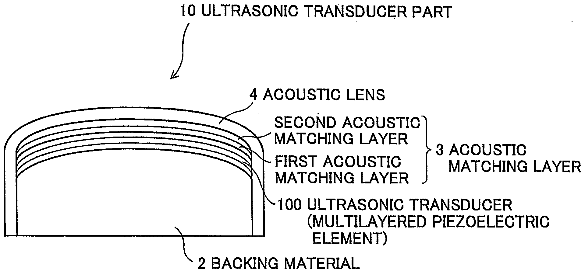
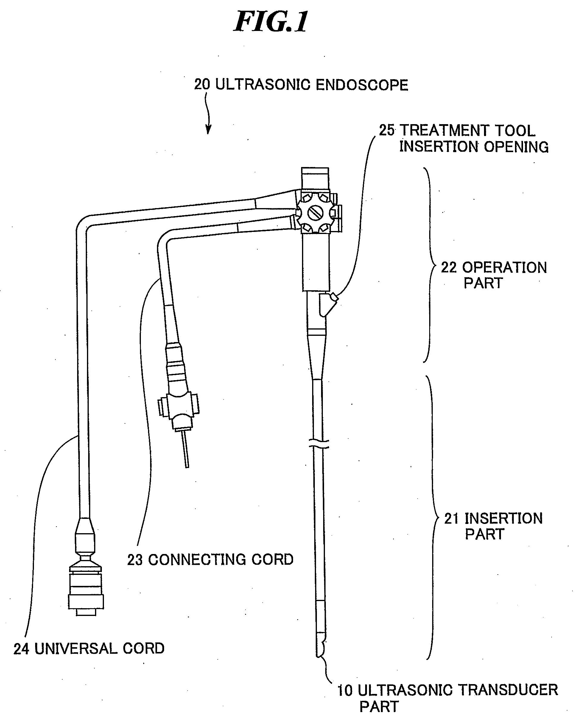
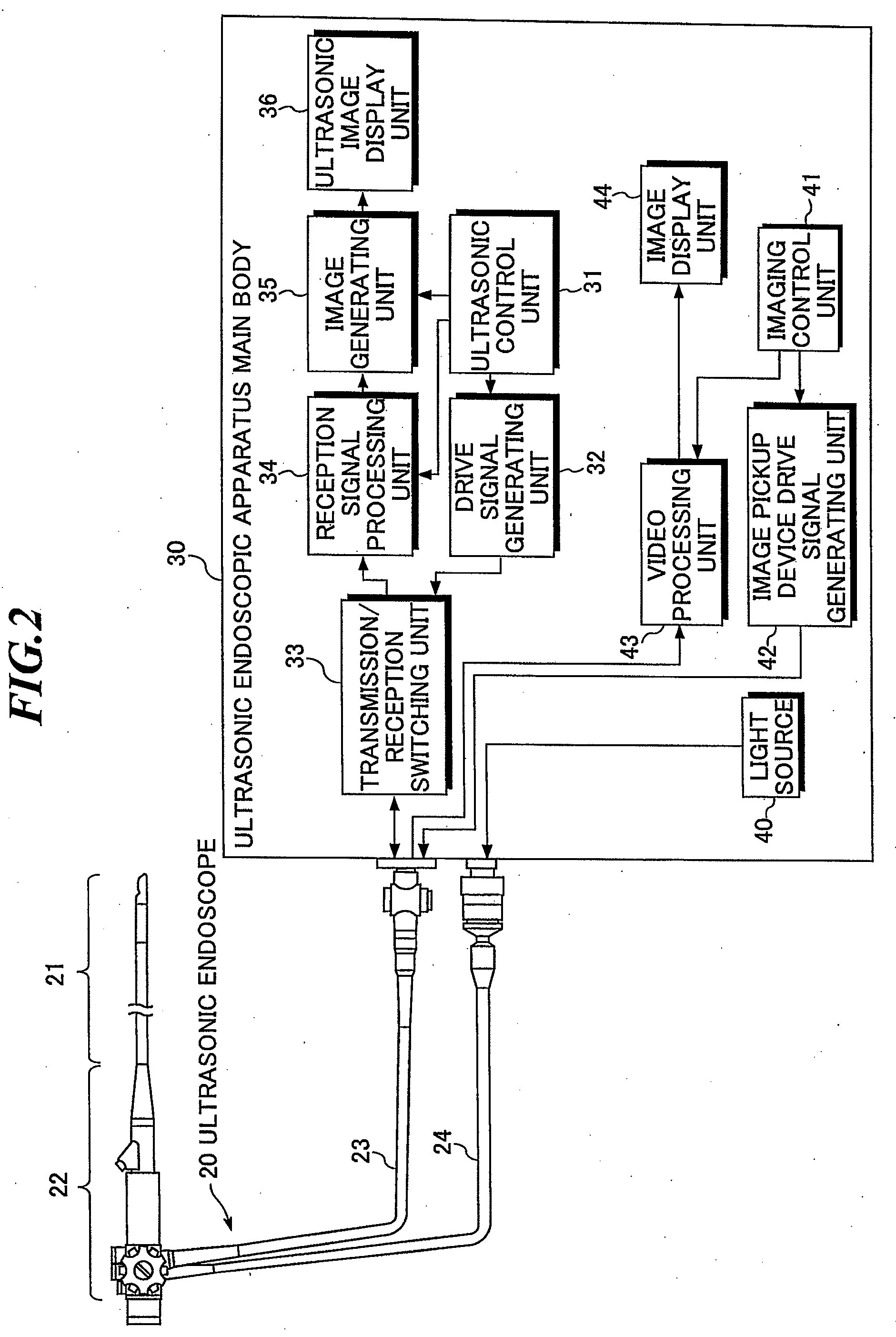
[0050]FIG. 3 is a side sectional view schematically showing the leading end of the insertion part of the ultrasonic endoscope according to the present invention. Further, FIG. 4 is a front sectional view along A-A′ in FIG. 3. As shown in FIGS. 3 and 4, the insertion part of the ultrasonic endoscope has plural (e.g., 64) ultrasonic transducers 1 for transmitting and receiving ultrasonic waves, a backing material 2 for supporting the plural ultrasonic transducers 1, an acoustic matching layer 3 for providing match of acoustic impedances between the plural ultrasonic transducers 1 and the object, an acoustic lens 4 for focusing ultrasonic waves in an elevation direction perpendicular to the arrangement direction (azimuth direction) of the ultrasonic transducers 1, a light guide output part 5 for outputting light, the image pickup device part (not shown) for optically imaging an affected part, and an exterior material 8 covering the respective parts.

[0051]The structure of the piezoelect...

second embodiment

[0078]As shown in FIG. 13, two shield foils 14 are provided along the two side surfaces of the ultrasonic transducer part 10, respectively. As is the case of the second embodiment, the shield foils 14 are formed of copper foils, for example. As shown in FIGS. 13 and 14, the shield foils 14 are connected and thermally coupled to the side highly heat conducting layers 12 via joint foils 15. The joint foils 15 may be formed integrally with the side highly heat conducting layers 12 or shield foils 14, or the side highly heat conducting layers 12, the shield foils 14, and the joint foils 15 may integrally be formed.

[0079]In the embodiment, as is the case of the first embodiment, the first signal line holding part 6 located under the backing material 2 is filled with the highly heat conducting resin and the highly heat conducting layer is provided at least on the bottom surface and the side surfaces of the first signal line holding part 6. According to the embodiment, heat diffusion from ...

fourth embodiment

[0086]In the embodiment, as is the case of the fourth embodiment, the first signal line holding part 6 located under the backing material 2 is filled with the highly heat conducting resin and the highly heat conducting layer is provided at least on the bottom surface and the side surfaces of the first signal line holding part 6. Further, the ultrasonic endoscope includes the bottom extended highly heat conducting layer 16 formed by extending the bottom highly heat conducting layer 11 provided on the bottom surface of the first signal line holding part 6 beyond the location of the rear highly heat conducting layers 13 toward the operation part side and the two shield foils 14 provided along the two side surfaces of the ultrasonic transducer part 10, respectively. According to the embodiment, improvements in heat dissipation by the bottom extended highly heat conducting layer 16 and the shield foils 14 are expected.

[0087]Next, the sixth embodiment of the present invention will be expl...


PUM


Abstract

In an ultrasonic endoscope, excessive temperature rise due to heat generated from ultrasonic transducers and/or an image pickup device is prevented. The ultrasonic endoscope includes: an ultrasonic transducer part including plural ultrasonic transducers for transmitting and receiving ultrasonic waves, and a backing material provided on a back of the plural ultrasonic transducers and having plural signal terminals provided on a surface opposite to the plural ultrasonic transducers; a signal line holding part including a highly heat conducting filler filling a space holding a group of shield lines electrically connected to the ultrasonic transducers via the plural signal terminals, and coupled to the backing material; and a highly heat conducting layer provided in contact with the signal line holding part, and thereby coupled to the signal line holding part.

Description

BACKGROUND OF THE INVENTION[0001]1. Field of the Invention[0002]The present invention relates to a heat dissipation structure of an ultrasonic endoscope including an ultrasonic probe to be used for body cavity examination of upper digestive organs, bronchial tube, and so on.[0003]2. Description of a Related Art[0004]In medical fields, various imaging technologies have been developed in order to observe the interior of an object to be inspected and make diagnoses. Among them, especially, ultrasonic imaging for acquiring interior information of the object by transmitting and receiving ultrasonic waves enables image observation in real time and provides no exposure to radiation unlike other medical image technologies such as X-ray photography or RI (radio isotope) scintillation camera. Accordingly, ultrasonic imaging is utilized as an imaging technology at a high level of safety in a wide range of departments including not only the fetal diagnosis in the obstetrics, but also gynecology...

Claims


Application Information

Patent Timeline
Patent Type & Authority Applications(United States)
IPC IPC(8): A61B8/14
CPCA61B8/12A61B8/445A61B8/4488
Inventor NAGANO, KAZUHIKOHYUGA, HIROAKIOSAWA, ATSUSHI
Owner FUJIFILM CORP
Why Eureka
Try Eureka