Method and an apparatus for localization of single dye molecules in the fluorescent microscopy

a single dye and fluorescent microscopy technology, applied in the field of detection and localization of single dye molecules in fluorescent microscopy, can solve the problems of insufficient resolution of cellular nanostructures to provide full functional information, limited image diffraction in light microscopy, and inability to overcome abbe-limits, etc., to achieve the effect of optimizing the localization process

Active Publication Date: 2009-09-24
UNIVERSITY OF HEIDELBERG
View PDF6 Cites 81 Cited by
  • Summary
  • Abstract
  • Description
  • Claims
  • Application Information

AI Technical Summary

Benefits of technology

[0026]An object of the invention is to provide a method and an apparatus with which the limit of the localization precision, respectively accurac

Problems solved by technology

It is known that due to the wave character of the light the images in light microscopy are diffraction limited.
Since numerous processes happen at a considerably smaller scale the overcoming of the Abbe-limit is one of the most difficult but the most important challenges in the modern light microscopy.
A serious problem in achieving this goal is that conventional light optical resolution is limited to about 200 nm laterally and 600 nm axially, meaning that cellular nanostructures cannot be adequately resolved to provide full functional information.
The predominantly confocal methods for improvement of the axial resolution are scanning techniques and are as such either too slow or do not fulfill the high optical requirements as such measurements.
The success of these methods is, however, restricted by the physical properties of the used dyes, respectively markers or labels and the optical properties of the observed sample, respectively slide preparation.
A three-dimensional obje

Method used


Image

  • Method and an apparatus for localization of single dye molecules in the fluorescent microscopy
  • Method and an apparatus for localization of single dye molecules in the fluorescent microscopy
  • Method and an apparatus for localization of single dye molecules in the fluorescent microscopy

Examples


example 1

Two-Dimensional SPDM Reconstruction

[0245]As a first application example, the SPDM microscopical method according described above was used for the two dimensional (2D) reconstruction of the distribution of membrane proteins. For this example cells of human breast cancer Cal-51 were labeled with yellow fluorescent proteins (YFP). During the SPDM imaging process, the YFP molecules were subjected to an appropriate physical modification based on reversible photobleaching as described above. For smoother appearance and to indicate the localization precision, the pixels (10 nm pixel size) corresponding to the positions and number of the localized fluorescent proteins were blurred via a Gaussian kernel with 15 nm standard deviation. In this example, the (x,y) width of the finest structures resolved (cellular protrusions) in the SPDM images amounted to about 50 nm-60 nm. The number of collected photons per molecule distribution (FIG. 9) allows to estimate the limiting localization accuracy d...

example 2

Three Dimensional SPDM / SMI Reconstruction

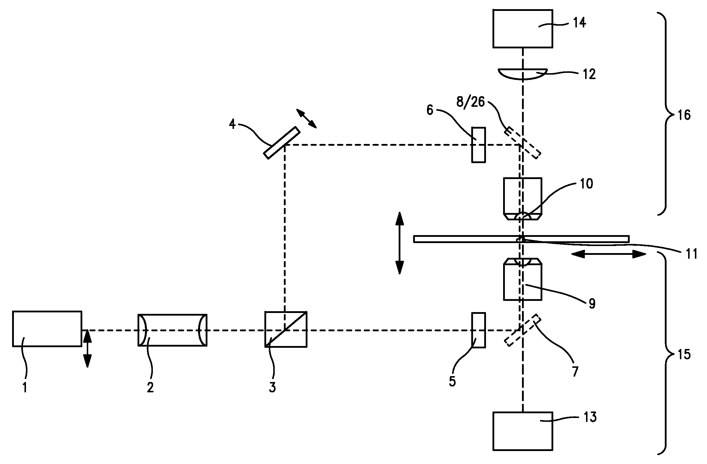
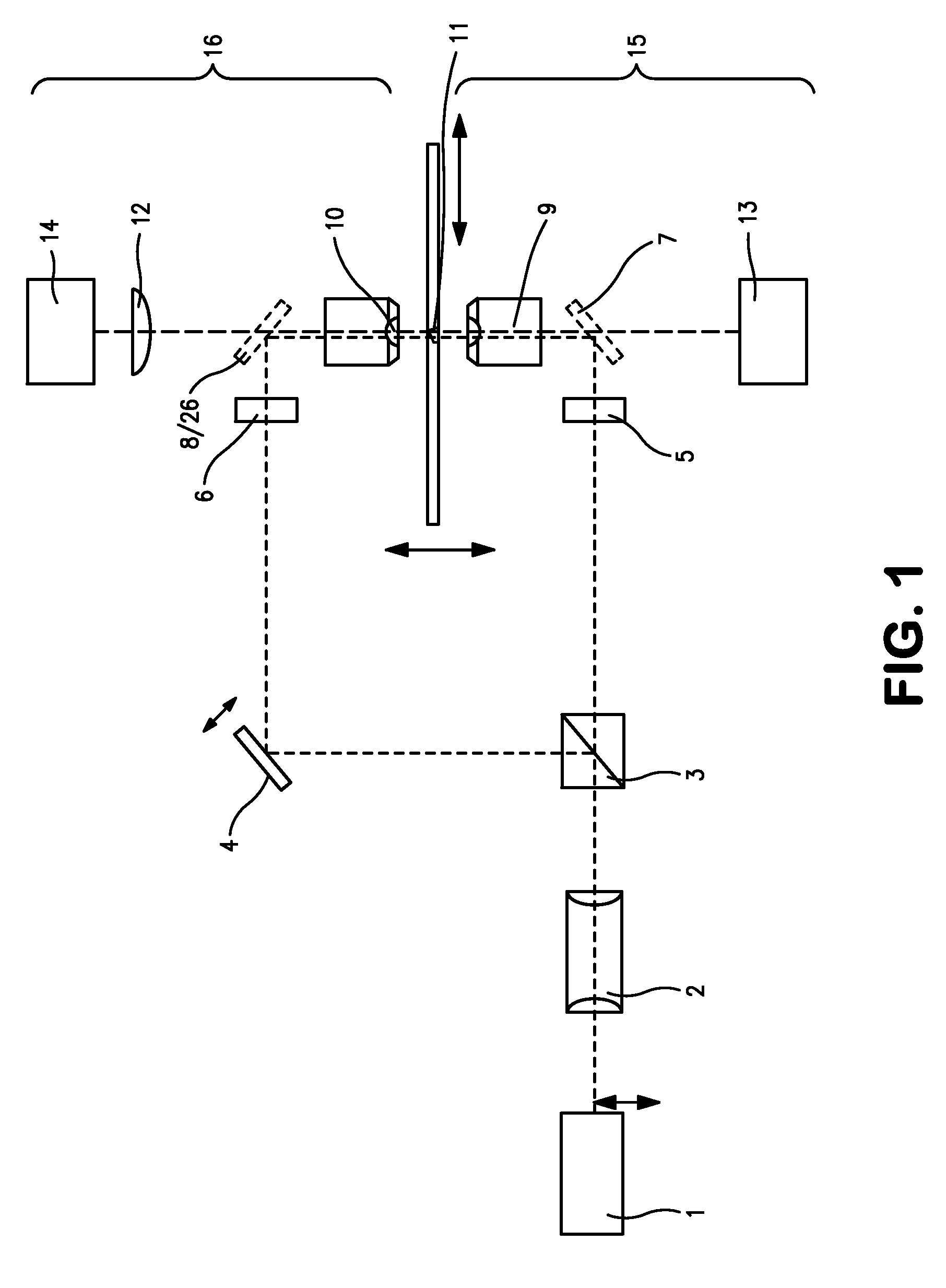
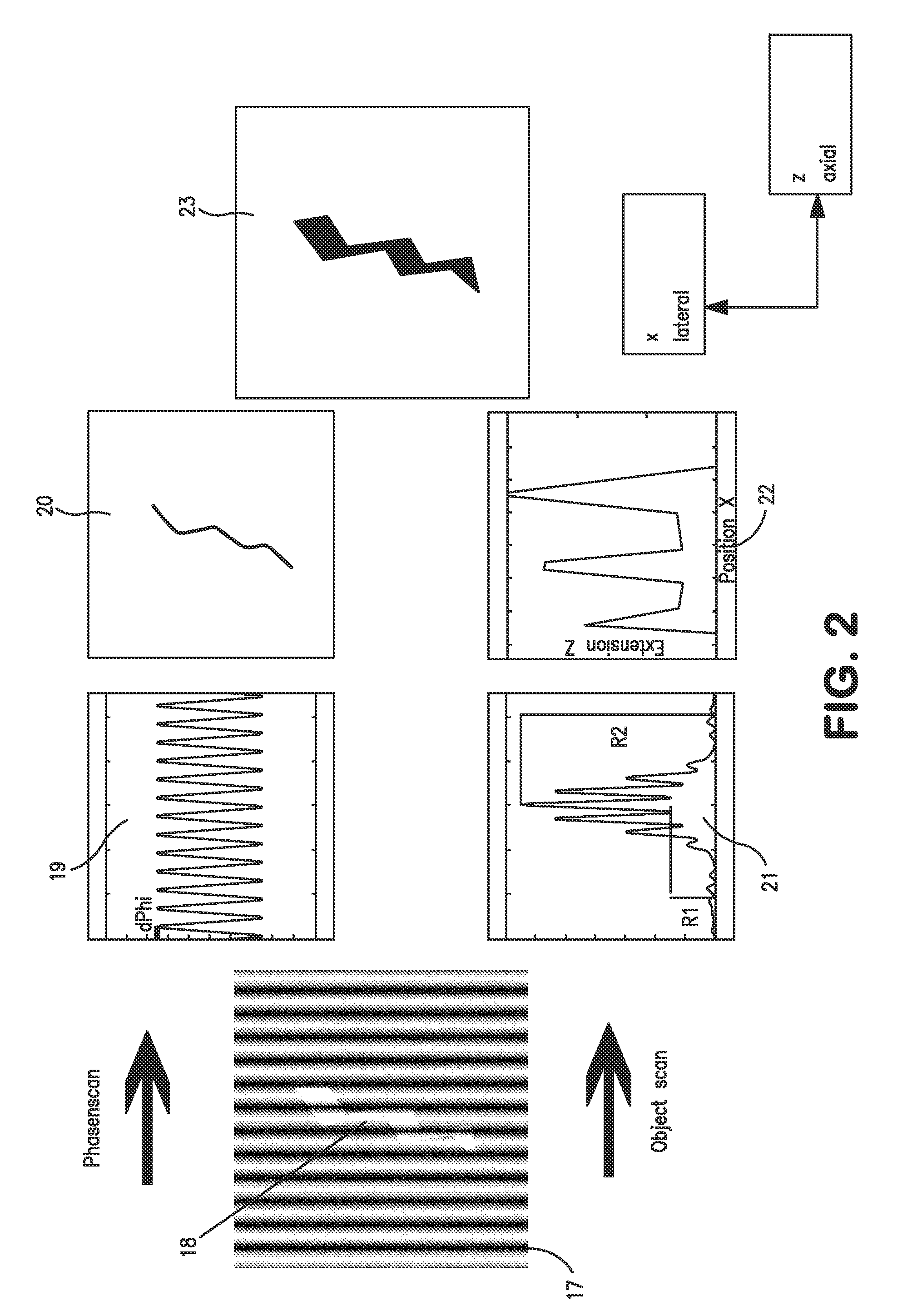
[0249]The second example relates to a three-dimensional SPDM / SMI reconstruction of a Cal-51 cell (plasma membrane labeled with physiochemically modified YFP) by first imaging in wide field mode with spatially modified illumination (cos2 intensity distribution along the optical axis). The standing wave field was moved with a step size Δz=25 nm for 5 μs (phase scan). The emission of the cellular plasma membrane protrusions was recorded for every Δz step. Compared to the experimentally effective wavelength (λexc / n≈330 nm) and the accuracy of the z-positioning of the piezo actuator 84 nm standard deviation), this process corresponds to a large oversampling. However, since the total acquisition time was about 20 seconds, there was no need to use larger step sizes or fewer steps.

[0250]By performing a single dimension Fourier transformation along the time axis, and knowing the wavelength of the light pattern (330 nm), the phase was determined for ev...


PUM


Abstract

A method and apparatus are provided for obtaining a sub-resolution spatial information of a sample labeled with at least one type fluorescent label. The sub-resolution spatial information has localization information about the positions of fluorescent molecules of the at least one type fluorescent label in at least one spatial direction. The method acquires localization image data by employing fluorescence localization microscopy. The acquired localization image data is processed to obtain the localization information about the positions of fluorescent molecules of the at least one type fluorescent label in at least one spatial direction. The step of processing includes determining in each of the detected images of the series the positions of the barycenters of the detected fluorescence emission distributions from the single fluorescent molecules of the one or more fluorescent labels in at least one spatial direction.

Description

CROSS-REFERENCE TO RELATED APPLICATIONS[0001]This application claims priority under 35 USC 119 on German Patent Appl. No. 10 2008 015 051.7 filed on Mar. 19, 2008 and further claims the benefit under 35 USC 120 based on International Appl. No. PCT / EP2008 / 009671 filed on Nov. 14, 2008. The disclosures of these two prior applications are incorporated herein by reference.BACKGROUND OF THE INVENTION[0002]1. Field of the Invention[0003]The invention relates to an apparatus (a microscope, respectively a microscopic system) and a method for obtaining a sub-resolution spatial information of one or more objects in a region of interest of an observed sample. In particular, the invention relates to the detection and localization of fluorescence molecules employed to label the measured objects.[0004]2. Description of the Related Art[0005]It is known that due to the wave character of the light the images in light microscopy are diffraction limited. This is manifested in that point-like objects a...

Claims


Application Information

Patent Timeline
IPC IPC(8): H04N7/18
CPCG01N21/6458G01N2021/6441G02B27/58G02B21/16G02B21/367G02B21/0076G01N21/6428
Inventor LEMMER, PAULCREMER, CHRISTOPHBADDELEY, DAVIDEIPEL, HEINZ
Owner UNIVERSITY OF HEIDELBERG
Why Eureka
Try Eureka