
Semiconductor light emitting device

a technology of semiconductor lasers and light emitting devices, which is applied in semiconductor lasers, electrical devices, laser details, etc., can solve the problems of poor efficiency of laser oscillation, and achieve the effect of improving luminous efficiency

Inactive Publication Date: 2009-09-24
ROHM CO LTD
View PDF15 Cites 50 Cited by
  • Summary
  • Abstract
  • Description
  • Claims
  • Application Information

AI Technical Summary

Benefits of technology

[0007]One of important characteristics of a semiconductor laser diode is a threshold current (oscillation threshold) for causing laser oscillation. Energy efficiency of the laser oscillation is improved as the threshold current is reduced.
[0009]Therefore, a laser diode having a major surface defined by a nonpolar plane such as an m-plane is proposed. When a laser diode is manufactured in a group III nitride semiconductor multilayer structure having major crystal growth surfaces defined by m-planes, for example, a light emitting layer emits light containing a large quantity of a polarization component parallel to the m-planes (more specifically, a polarization component in an a-axis direction). Thus, a large ratio of the light emitted in the light emitting layer can contribute to laser oscillation, whereby efficiency of the laser oscillation is improved and the threshold current can be reduced.
[0010]When the light emitting layer has a quantum well structure (more specifically, a quantum well structure containing In), separation of carriers resulting from spontaneous piezoelectric polarization in a quantum well is suppressed, and hence the luminous efficiency is increased. When major surfaces of crystal growth are defined by m-planes, crystals can be extremely stably grown and crystallinity can be improved as compared with a case of defining the major surfaces of crystal growth by c-planes or other crystal planes. Consequently, a high-performance laser diode can be manufactured.
[0012]If an InGaN quantum well layer and an InGaN guide layer are coherently grown on an m-plane GaN layer, however, in-plane anisotropic compressive stress acts on the layers. More specifically, relatively large compressive stress is developed in a direction perpendicular to a c-axis, i.e., along an a-axis direction. This is because the a-axis lattice constant of InGaN is greater than that of GaN. If the In composition in or the thickness of the InGaN quantum well layer or the InGaN guide layer is increased, therefore, crystal defects are formed along an a-axis. The crystal defects are observed with a fluorescent microscope as dark lines parallel to the a-axis. Therefore, the defects are conceivably nonluminous. If such nonluminous defects can be suppressed, the luminous efficiency can conceivably be further improved.
[0014]Accordingly, an object of the present invention is to provide a semiconductor light emitting device improved in luminous efficiency with group III nitride semiconductors having major growth surfaces defined by nonpolar planes or semipolar planes.

Problems solved by technology

Therefore, efficiency of laser oscillation is not necessarily excellent, and hence the semiconductor laser diode should be improved in order to reduce the threshold current.

Method used


Image

  • Semiconductor light emitting device
  • Semiconductor light emitting device
  • Semiconductor light emitting device

Examples


examples

[0197]While the present invention is now described with reference to Examples, the present invention is not restricted to the following Examples.

examples 1 to 3

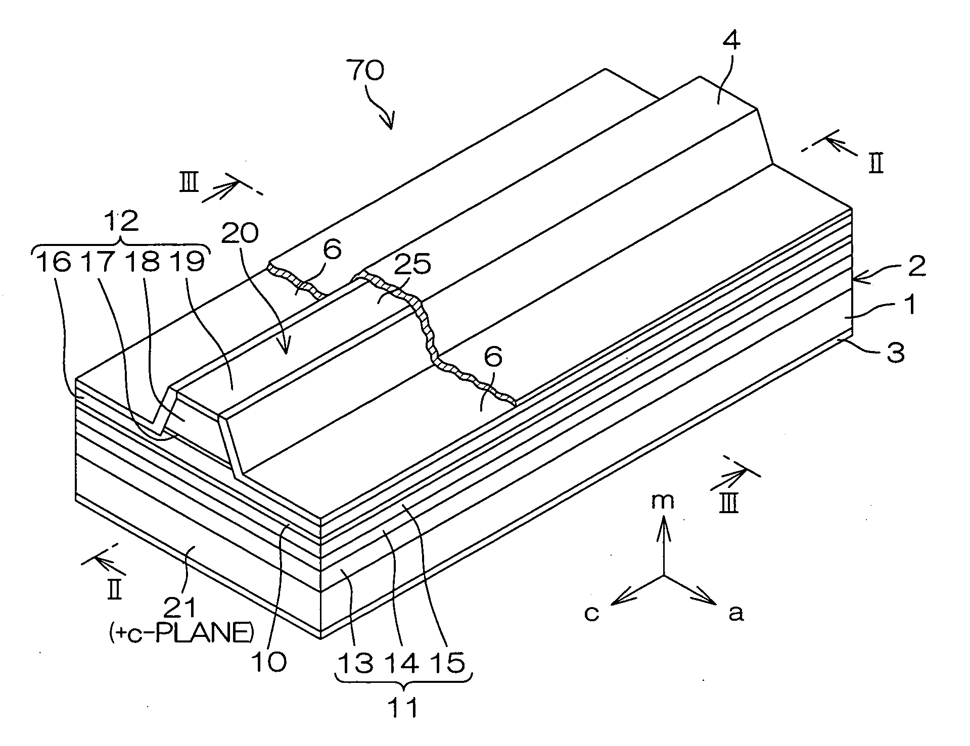
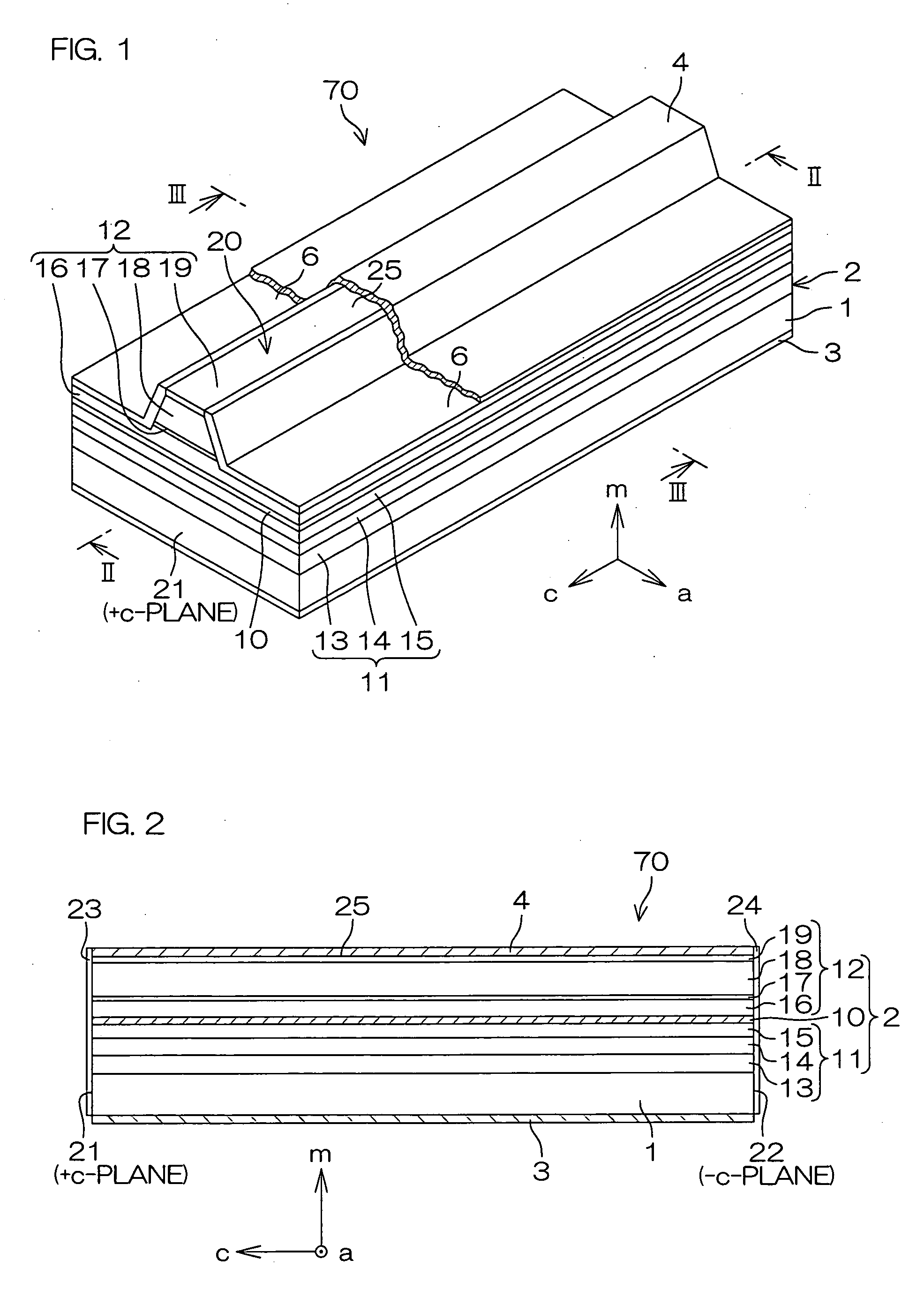
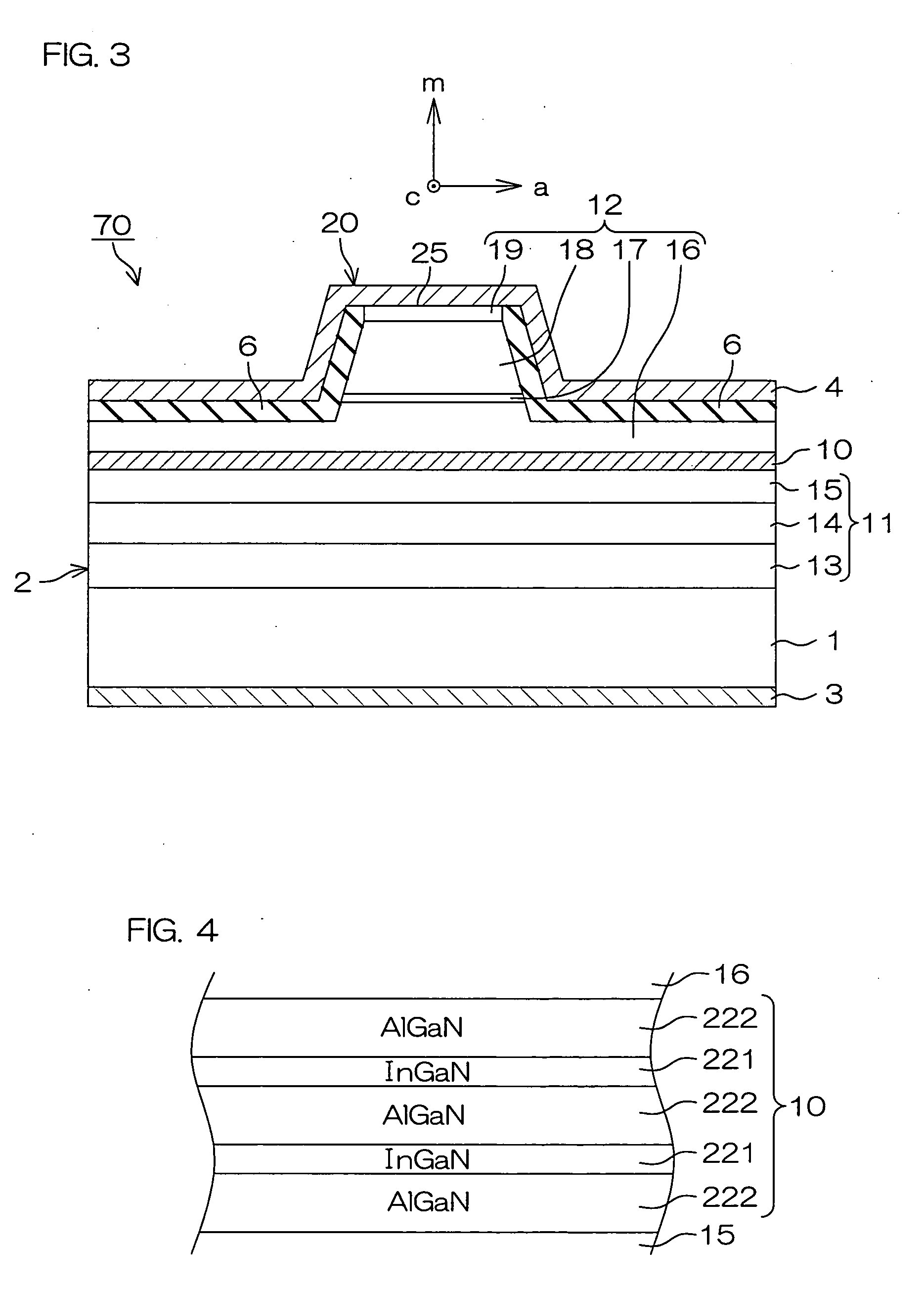
[0198]In each of Examples 1 to 3, a semiconductor laser diode having the structure shown in FIGS. 1 to 3 was prepared according to the manufacturing steps described with reference to the first embodiment.

[0199]In Example 1, a p-type electrode made of Pt / Au metal was not annealed after formation thereof. In Examples 2 and 3, p-type electrodes were annealed at temperatures of 200° C. and 400° C. respectively.

examples 4 to 7

[0200]In each of Examples 4 to 7, a semiconductor laser diode having the structure shown in FIGS. 1 to 3 was prepared according to the manufacturing steps described with reference to the first embodiment, except that an electrode made of Pd / Au metal having a two-layer structure consisting of a lower layer containing Pd and an upper layer containing Au was formed as a p-type electrode.

[0201]In Example 4, the p-type electrode made of Pd / Au metal was not annealed after formation thereof. In Examples 5 to 7, the p-type electrodes were annealed at temperatures of 200° C., 400° C. and 600° C. respectively.


PUM


Abstract

A semiconductor light emitting device is made of a group III nitride semiconductor having a major growth surface defined by a nonpolar plane or a semipolar plane, and has a quantum well layer containing In in a light emitting layer. A strain compensation layer made of a group III nitride semiconductor containing Al and having a lattice constant smaller than the lattice constant of the quantum well layer in a strain-free state is interposed in the light emitting layer of a quantum well structure having the quantum well layer and a barrier layer or in an adjacent layer adjacent to the light emitting layer.

Description

BACKGROUND OF THE INVENTION[0001]1. Field of the Invention[0002]The present invention relates to a semiconductor light emitting device (a light emitting diode, a laser diode or the like) employing group III nitride semiconductors.[0003]2. Description of Related Art[0004]Group III-V semiconductors employing nitrogen as a group V element are referred to as group III nitride semiconductors, and typical examples thereof include aluminum nitride (AlN), gallium nitride (GaN) and indium nitride (InN), which can be generally expressed as AlXInYGa1-X-YN (0≦x≦1, 0≦y≦1 and 0≦X+Y≦1).[0005]A short wavelength laser source emitting a blue or green laser beam is increasingly employed in the fields of high-density recording in an optical disk represented by a DVD, image processing, medical instruments, measuring instruments and the like. Such a short wavelength laser source includes a laser diode employing GaN semiconductors, for example.[0006]A GaN semiconductor laser diode is manufactured by growi...

Claims


Application Information

Patent Timeline
IPC IPC(8): H01S5/00
CPCB82Y20/00H01S5/0283H01S5/2009H01S5/34333H01S5/3202H01S5/3406H01S5/2201H01S5/32025H01S5/320275
Inventor KUBOTA, MASASHIOKAMOTO, KUNIYOSHITANAKA, TAKETOSHITANAKA, YOSHINORI
Owner ROHM CO LTD
Learn More