Fuel cell system, estimation device of amount of anode gas to be generated and estimation method of amount of anode gas to be generated

a fuel cell and anode gas technology, applied in the field of fuel cell systems, can solve the problems of high detection time requirements, achieve the effects of low power generation efficiency, fast and correct extraction, and reduce exhaust hydrogen concentration

Active Publication Date: 2009-10-29
TOYOTA JIDOSHA KK
View PDF7 Cites 24 Cited by
  • Summary
  • Abstract
  • Description
  • Claims
  • Application Information

AI Technical Summary

Benefits of technology

[0008]In view of the above-mentioned situation, the present invention has been developed, and an object thereof is to provide a fuel cell system capable of sufficiently reducing an exhaust hydrogen concentration even in a case where a fuel cell is operated in a state of a low power generation efficiency. Furthermore, an object of the present invention is to provide a technology capable of quickly and correctly obtaining a concentration of a hydrogen-off gas to be discharged from the side of a cathode.
[0014]Moreover, in the above constitution, it is a preferable configuration that the oxidation gas supply source is an air compressor and that the control means controls the amount of the oxidation gas to be discharged while keeping the pressure regulation valve to be fully opened in accordance with the amount of the oxidation gas required for the power generation of the fuel cell.
[0028]As described above, according to the present invention, even in a case where the fuel cell is operated in a state of a low power generation efficiency, an exhaust hydrogen concentration can sufficiently be reduced. According to the present invention, the concentration of the hydrogen-off gas or the like to be discharged from the cathode side can quickly and correctly be obtained.

Problems solved by technology

However, in a case where a fuel cell is operated in a state of a low power generation efficiency, not only hydrogen is discharged from an anode but also hydrogen (mainly pumping hydrogen) is discharged from a cathode, and hydrogen in excess of a regulated range is sometimes discharged from a system.
Moreover, the above conventional detection method of a concentration of a hydrogen-off gas has a problem that the concentration cannot be detected until the hydrogen-off gas reaches a hydrogen sensor and that much time is required for the detection.

Method used


Image

  • Fuel cell system, estimation device of amount of anode gas to be generated and estimation method of amount of anode gas to be generated
  • Fuel cell system, estimation device of amount of anode gas to be generated and estimation method of amount of anode gas to be generated
  • Fuel cell system, estimation device of amount of anode gas to be generated and estimation method of amount of anode gas to be generated

Examples


first embodiment

A. First Embodiment

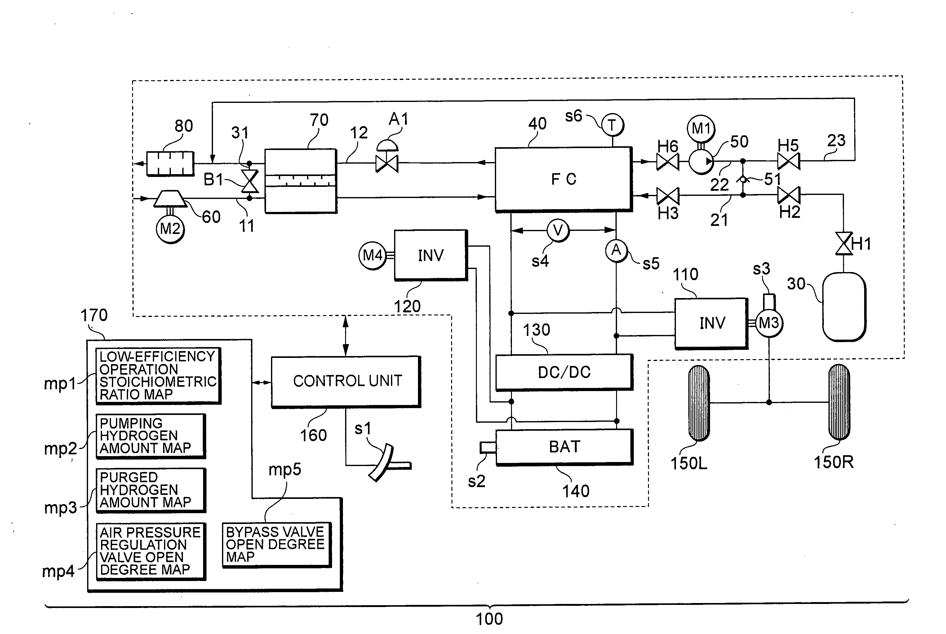
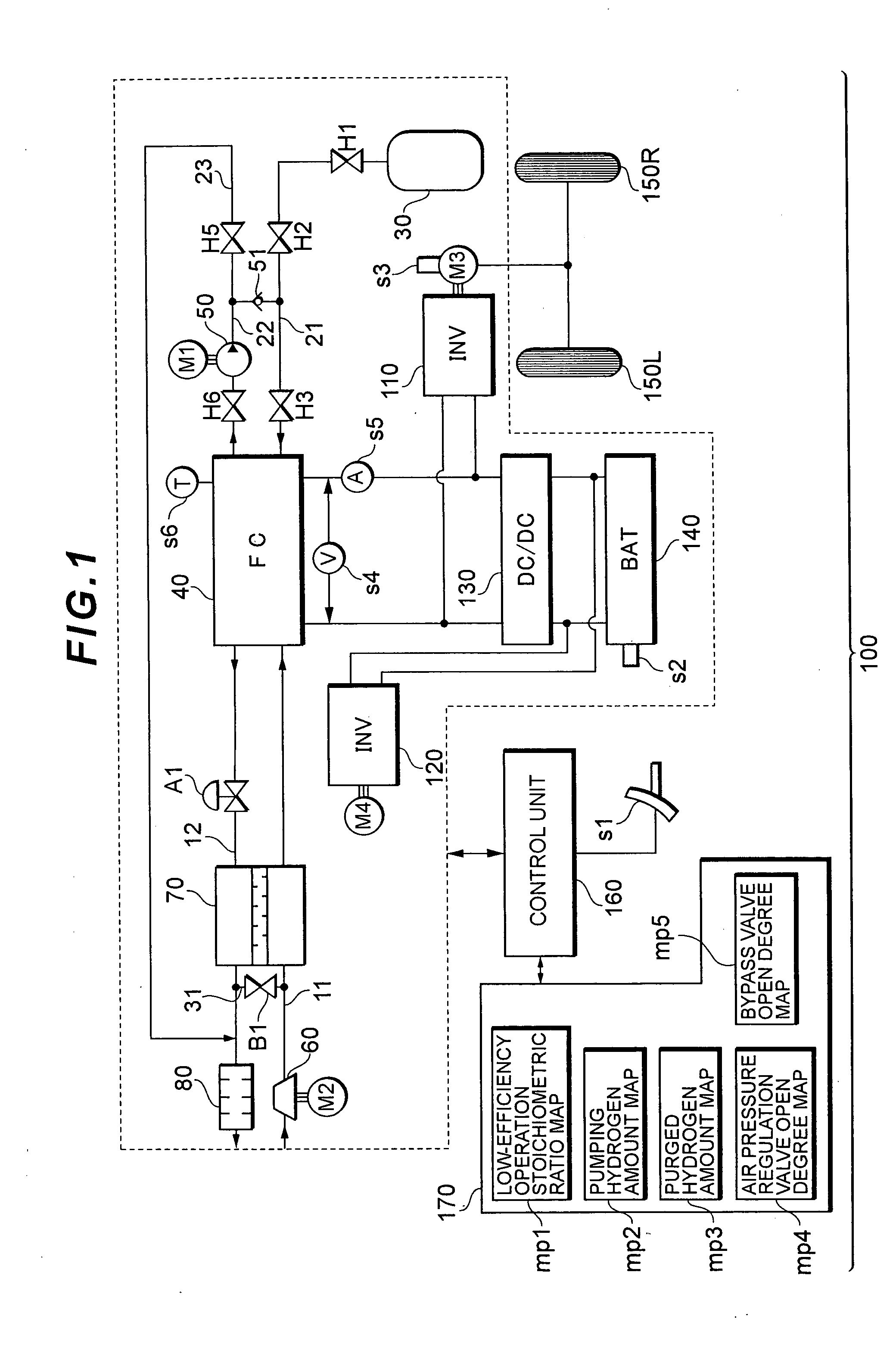
[0048]FIG. 1 is a diagram showing a constitution of a main part of a fuel cell system 100 according to the present embodiment. In the present embodiment, a fuel cell system is assumed which is to be mounted on vehicles such as a fuel cell car (FCHV), an electric car and a hybrid car, but the system is also applicable to not only the vehicles but also various mobile objects (e.g., a ship, an airplane, a robot, etc.) and a stationary power source.

[0049]The fuel cell system 100 includes a fuel gas circulation supply system and an oxidation gas supply system.

[0050]The fuel gas circulation supply system includes a fuel gas supply source 30, a fuel gas supply path 21, a fuel cell 40, a fuel gas circulation path 22 and an anode-off gas channel 23, and the oxidation gas supply system includes an air compressor 60, an oxidation gas supply path 11 and a cathode-off gas channel 12.

[0051]The fuel cell 40 is means for generating a power from a supplied reactive gas (a fuel gas...

second embodiment

B. Second Embodiment

[0087]FIG. 5 is a diagram showing a constitution of a main part of a fuel cell system 1000 according to a second embodiment. In the same manner as in the first embodiment described above, also in the second embodiment, the fuel cell system is assumed which is to be mounted on vehicles such as a fuel cell car (FCHV), an electric car and a hybrid car, but the system is also applicable to not only the vehicles but also various mobile objects (e.g., a ship, an airplane, a robot, etc.) and a stationary power source.

[0088]A fuel cell 400 is means for generating a power from a supplied reactive gas (a fuel gas and an oxidation gas), and has a stack structure in which a plurality of single cells including an MEA (a film / electrode bonded material) and the like are laminated in series. Specifically, fuel cells of various types such as a solid polymer type, a phosphoric acid type and a dissolving carbonate type may be used. The fuel gas including hydrogen is supplied from a...

third embodiment

C. Third Embodiment

[0124]FIG. 9 is a diagram showing a constitution around a fuel cell according to a third embodiment. In the same manner as in the above embodiments, even in the third embodiment, a fuel cell system is assumed which is to be mounted on vehicles such as a fuel cell car (FCHV), an electric car and a hybrid car, but the system is also applicable to not only the vehicles but also various mobile objects (e.g., a ship, an airplane, a robot, etc.) and a stationary power source.

[0125]A fuel cell2400 shown in FIG. 9 is provided with a cell monitor 460-k (1≦k≦n) for each cell 450-k (1≦k≦n). The present embodiment is characterized in that an amount of pumping hydrogen to be generated (or a concentration of pumping hydrogen) is estimated based on a cell voltage detected by the cell monitor 460-k. This will hereinafter be described in detail.

[0126]Each cell monitor 460-k detects a voltage value (the cell voltage) of the corresponding cell 450-k to supply the value to a control ...


PUM

PropertyMeasurementUnit
concentrationaaaaaaaaaa
temperatureaaaaaaaaaa
output voltageaaaaaaaaaa

Abstract

There is disclosed a fuel cell system or the like capable of sufficiently reducing an exhaust hydrogen concentration even in a case where a fuel cell is operated in a state of a low power generation efficiency. A bypass valve is arranged between an oxidation gas supply path and a cathode-off gas channel. In a state in which supply of an oxidation gas to a cathode falls short, pumping hydrogen is included in a cathode-off gas. Therefore, a valve open degree of the bypass valve is regulated, and a flow rate of bypass air is regulated to control the exhaust hydrogen concentration.

Description

TECHNICAL FIELD[0001]The present invention relates to a fuel cell system, and a technology for estimating an amount of an anode gas to be generated in a cathode of a fuel cell.BACKGROUND ART[0002]A fuel cell mounted on a fuel cell car and the like generates a power by use of a fuel gas including hydrogen to be supplied to an anode and an oxidation gas including oxygen to be supplied to a cathode. A hydrogen-off gas to be discharged from the fuel cell is mixed and diluted with an oxygen-off gas, and discharged from the car in a state in which a hydrogen concentration is reduced. To discharge such a hydrogen-off gas, the gas needs to be sufficiently diluted so that a high concentration of hydrogen is not discharged (see, e.g., Patent Document 1).[0003]Moreover, to sufficiently dilute the gas so that the high concentration of hydrogen is not discharged, the concentration of the hydrogen-off gas needs to be detected with a good precision. As a method of detecting such an hydrogen-off ga...

Claims


Application Information

Patent Timeline
Patent Type & Authority Applications(United States)
IPC IPC(8): H01M8/04H01M2/02H01M50/77
CPCH01M8/04089Y02E60/50H01M8/04149H01M8/04231H01M8/04238H01M8/04268H01M8/04432H01M8/04462H01M8/0447H01M8/04559H01M8/04746H01M8/04761H01M8/04776H01M8/04992H01M8/0662H01M8/04141Y02P70/50H01M8/04H01M8/10
Inventor IMANISHI, HIROYUKIMANABE, KOTAOGAWA, TOMOYATEJIMA, GONAGANUMA, YOSHIAKINOTO, HIRONORI
Owner TOYOTA JIDOSHA KK
Why Eureka
Try Eureka