Method of Deep Sewage Treatment without Sludge Discharge and Device Therefor

a sewage treatment and deep sewage technology, applied in biological water/sewage treatment, separation processes, filtration separation, etc., can solve the problems of affecting the development of these professional domains, affecting the living environment, and unsatisfactory total processing results, etc., to achieve remarkable sewage treatment effect, reduce area, and reduce the effect of area

Active Publication Date: 2009-11-05
CHIANG MING HUI
View PDF4 Cites 32 Cited by
  • Summary
  • Abstract
  • Description
  • Claims
  • Application Information

AI Technical Summary

Benefits of technology

[0015]Backflow device on whose pipe there is a control valve is provided among anaerobic and sludge backflow tank, sludge and clarified water separation tank, separation tank, release tank, and aerobic biological process tank or aeration tank, so that the sludge and sewage therein can be backflown to aerobic biological process tank or the aeration tank by backflow device. The said primary clarifier with bar screen is provided with bar screen and strainer. The said primary sedimentation tank by neutralization and the said primary clarifier with bar screen are connected by a water pump with control valve. Electrical water pump is provided between the said primary sedimentation tank by neutralization and the aeration tank, so that the sewage to be treated in the primary sedimentation tank by neutralization is pumped to the aeration tank. Pipes connected with each other are provided between the said aeration tank and the aerobic biological process tank, so that the sewage in the aeration tank is unaffectedly flown into the aerobic biological process tank. Electrically water pump is provided on the pipe between the said aerobic biological process tank and the first anaerobic and sludge backflow tank. We can set many said anaerobic and sludge backflow tanks according to our need, which are adjacent and connected with each other, in every whose center an overflow weir is provided and the above side of the overflow weir is zigzag-shaped, nearly in every whose bottom is provided backflow device, on whose pipe a control valve is provided and which connects aerobic biological process tank and the aeration tank respectively. In the center of the said sludge and clarified water separation tank a pipe which introduces sludge is provided, and in the bottom of the said sludge and clarified water separation tank backflow device is provided. We can set many said separation tanks and release tanks according to our need, which are adjacent and connected with each other, in every whose bottom is provided with sludge backflow device, on whose pipe control valve is provided and which connects with aerobic biological process tank. A water pipe with a control valve is provided on the discharge outlet of the said release tank. In addition, the said functional tanks can be laminatedly overlapped to reduce the area. Because the dimension of the said the primary clarifier with bar screen, the primary sedimentation tank by neutralization, the aeration tank, and the aerobic biological process tank need be larger, they can be set downstream in the mode of excavating to satisfy the requirement of the dimension. The said anaerobic and sludge backflow tank, sludge and clarified water separation tank, separation tank and release tank can be set upstream according to our need, and the sludge and clarified water separation tank can be relatively larger.
[0016]In operation, before coming into the primary sedimentation tank by neutralization, the sewage is filtered by bar screen and strainer, to intercept the suspension of pollutant, and to protect the devices such as water pump unit used in the following process. The sewage coming into the primary sedimentation tank by neutralization is sampled, detected, added a suitable preparation to neutralize to make PH value be between 6-9. The sewage coming into the aeration tank is sampled, detected, added a suitable sewage treatment agent of LTC-A developed by Shanghai LianTan Chemical Ltd according to the detected result, which is pumped into the aerobic biological process tank together with the sewage in the aeration tank. The blaster unit supplies oxygen to the sewage in the primary sedimentation tank by neutralization, the aeration tank, and aerobic biological process tank respectively, so that fully with the various aerobic microorganism in the sewage the colloid-shaped and dissoluted organic matter in the sewage is oxidized and decomposed to microorganism, CO2 and H2O in the condition of full oxygen to primarily pure the sewage. The primarily pured water processed by aerobic treatment is pumped to the first anaerobic and sludge backflow tank by the power device to be anaerobic processed, so that in the case of no dissociative oxygen anaerobic microorganism in the sewage makes hydrolysis and fermentation to the organic matter, and exchanges carbohydrate, protein and fat into monosaccharide, amino acid, fatty acid CO2 and H2O, then degenerates to methane. The rela...

Problems solved by technology

Currently, because the industrial waste water generated in some professional domains has many shortcomings such as large amount of discharge and high density of pollutant, which is causing more and more serious pollution to the water environment and destroying the ecological equilibrium of all the world, it both seriously effects human living environment and hinders the development of these professional domains.
Though they have effect on improving some...

Method used


Image

  • Method of Deep Sewage Treatment without Sludge Discharge and Device Therefor
  • Method of Deep Sewage Treatment without Sludge Discharge and Device Therefor
  • Method of Deep Sewage Treatment without Sludge Discharge and Device Therefor

Examples


Embodiment Construction

[0032]Hereinafter, the present invention will be described with reference to the accompanying drawings and an embodiment.

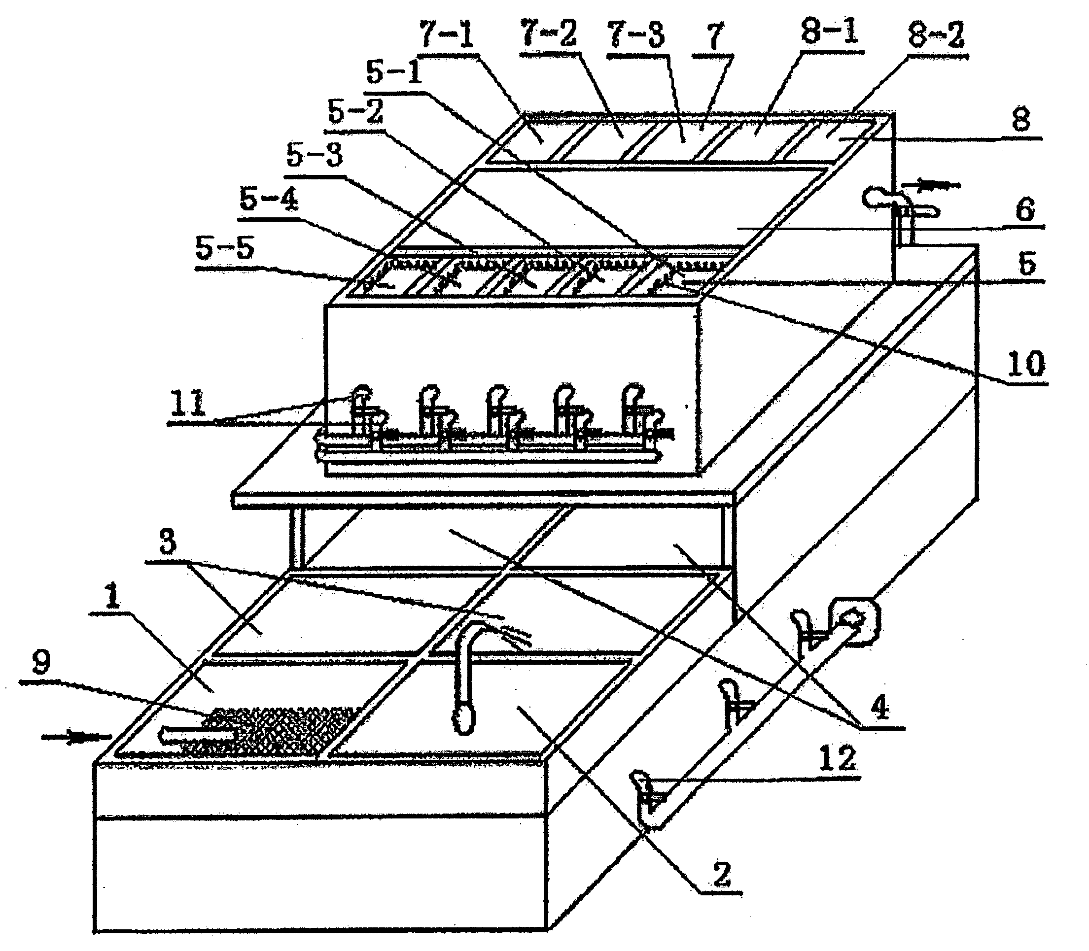
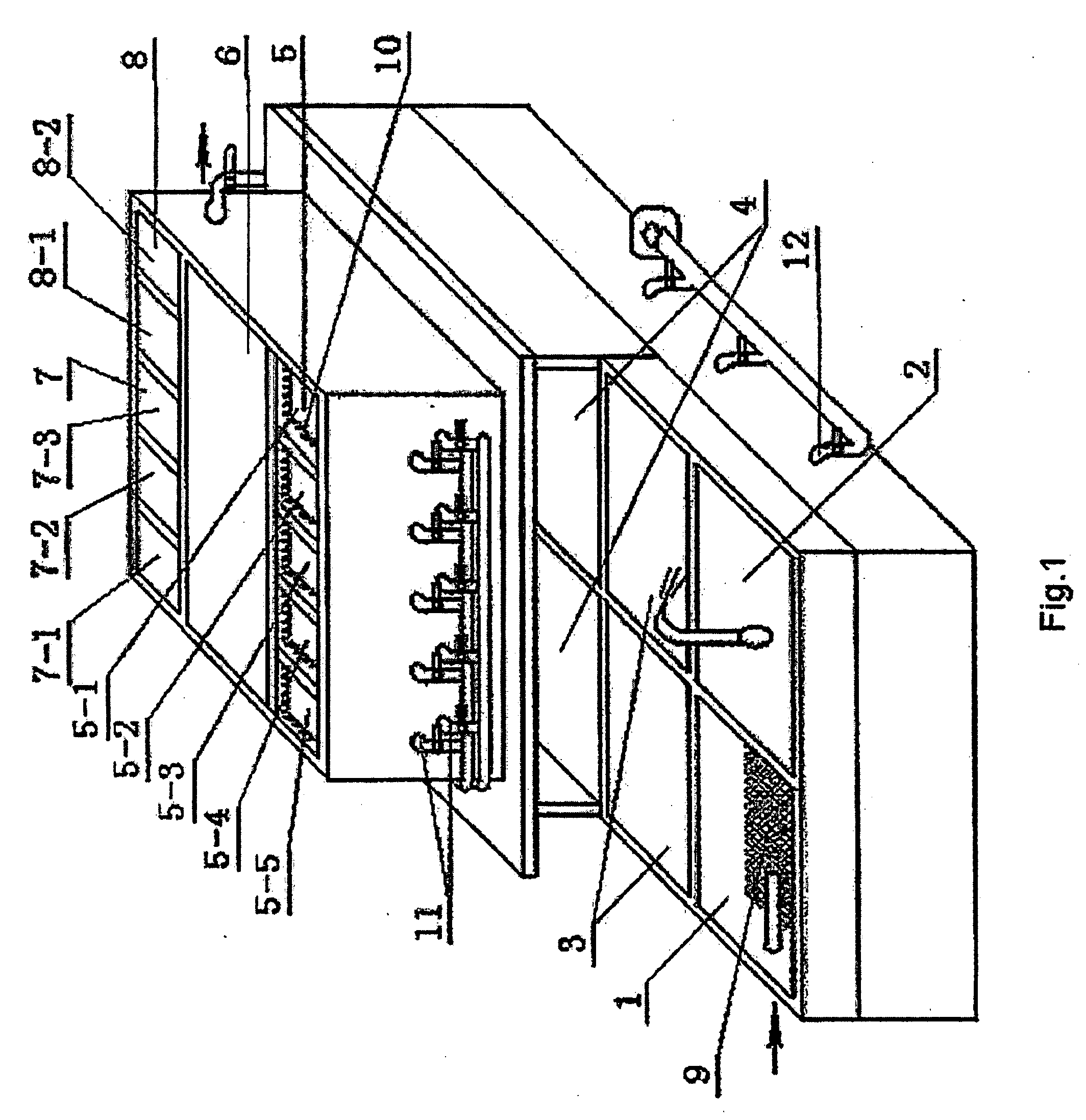
[0033]Referring to FIG. 1, the device of deep sewage treatment without sludge discharge according to the present invention mainly includes functional tanks and power, pump and control mechanism, in which: functional tanks are arranged in the updown laminating form and comprise primary clarifier 1 with bar screen, primary sedimentation tank by neutralization 2, aeration tank 3, and aerobic biological process tank 4, which locate downstream, and anaerobic and sludge backflow tank 5, sludge and clarified water separation tank 6, separation tank 7, and release tank 8, which locate upstream. Power, pump and control mechanism comprises blaster of supplying oxygen, electrically water pump, and control valve. The said primary clarifier 1 is provided with bar screen and strainer 9. The said primary sedimentation tank by neutralization 2 and the said primary clarifier 1 wit...


PUM

PropertyMeasurementUnit
Temperatureaaaaaaaaaa
Densityaaaaaaaaaa
Adsorption entropyaaaaaaaaaa

Abstract

A deeply sewage treating method and apparatus without sludge discharging is disclosed by means of the physical, chemical and biological methods. Proper sewage treating agent with powerful adsorbing capacity, organic matter decomposing and oxidizing capacity and settling capacity is selected based on the quantity of sewage and pollutant characteristic of the sewage to be treated. Sewage is treated through an integrative function tank that comprises a grille primary tank (1), a settling tank (2), high concentration aeration tank (3), aerobic biological tank (4), anaerobic sludge returning tank (5), a sludge and cleaning water separating tank (6), separating tank (7), and pouring tank (8). Sewage is subjected to physical filtering, chemical regulation of pH value, aerating, biological treatment, settling and filtering, so that organic pollutant is converted into microbe that is oxidized and decomposed into CO2, H2O, NH3 and small amount of excess sludge for inside circulating treatment. The treated water reaches the draining standard.

Description

FIELD OF THE INVENTION[0001]The present invention relates to a technical field of environmental protection, particularly to a method of deep sewage treatment without sludge discharge by comprehensively adopting physical, chemical and biological sewage treatment technology and device thereof.BACKGROUND OF THE INVENTION[0002]Currently, because the industrial waste water generated in some professional domains has many shortcomings such as large amount of discharge and high density of pollutant, which is causing more and more serious pollution to the water environment and destroying the ecological equilibrium of all the world, it both seriously effects human living environment and hinders the development of these professional domains. Because the problem of sewage treatment and the ecological environmental protection is considered more and more important in various professional domains, massive persons and money have been used in the topic research, and many research results have been a...

Claims


Application Information

Patent Timeline
IPC IPC(8): B01D35/157C02F3/30
CPCC02F1/66C02F3/301C02F3/30C02F3/1221Y02W10/10
Inventor CHIANG, MING-HUI
Owner CHIANG MING HUI
Why Eureka
Try Eureka