
Method and apparatus for producing nitrogen trifluoride

Inactive Publication Date: 2009-11-12
SHOWA DENKO KK
View PDF11 Cites 2 Cited by
  • Summary
  • Abstract
  • Description
  • Claims
  • Application Information

AI Technical Summary

Benefits of technology

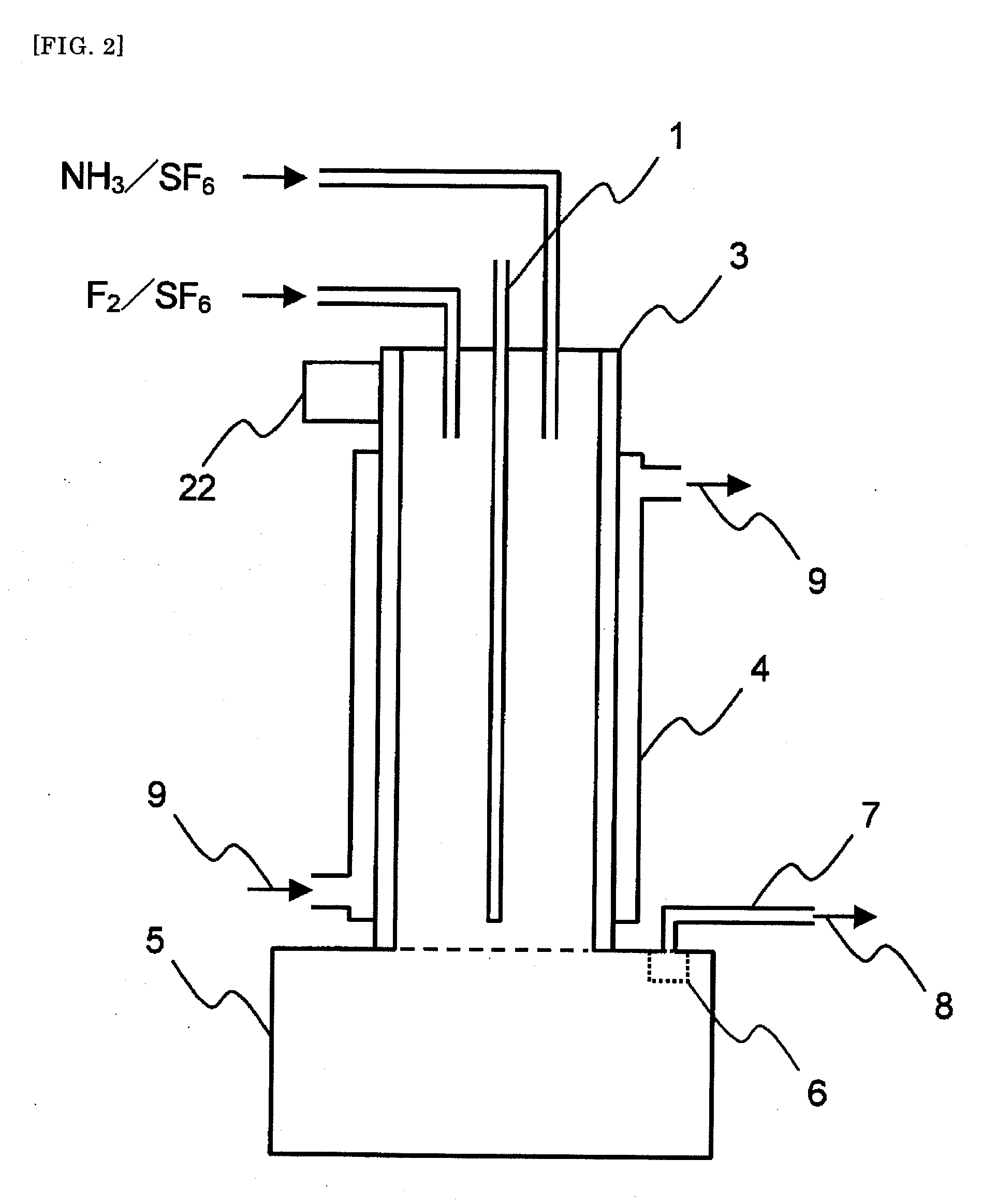
[0059]The present invention addresses the problems encountered in the production of NF3 by the reaction between an F2 gas and an NH3 gas, for example decreased yield caused by the clogging of a reactor and pipes. In the present invention, the raw material gases are fed into and reacted in a tubular reactor, which is equipped with a device for removing a solid product which is mainly composed of ammonium fluoride and/or acidic ammonium fluoride and which is attached to an inner wall of the tubular reactor. The method according to this embodiment of the invention can produce NF3 continuously in a good yield and economically.
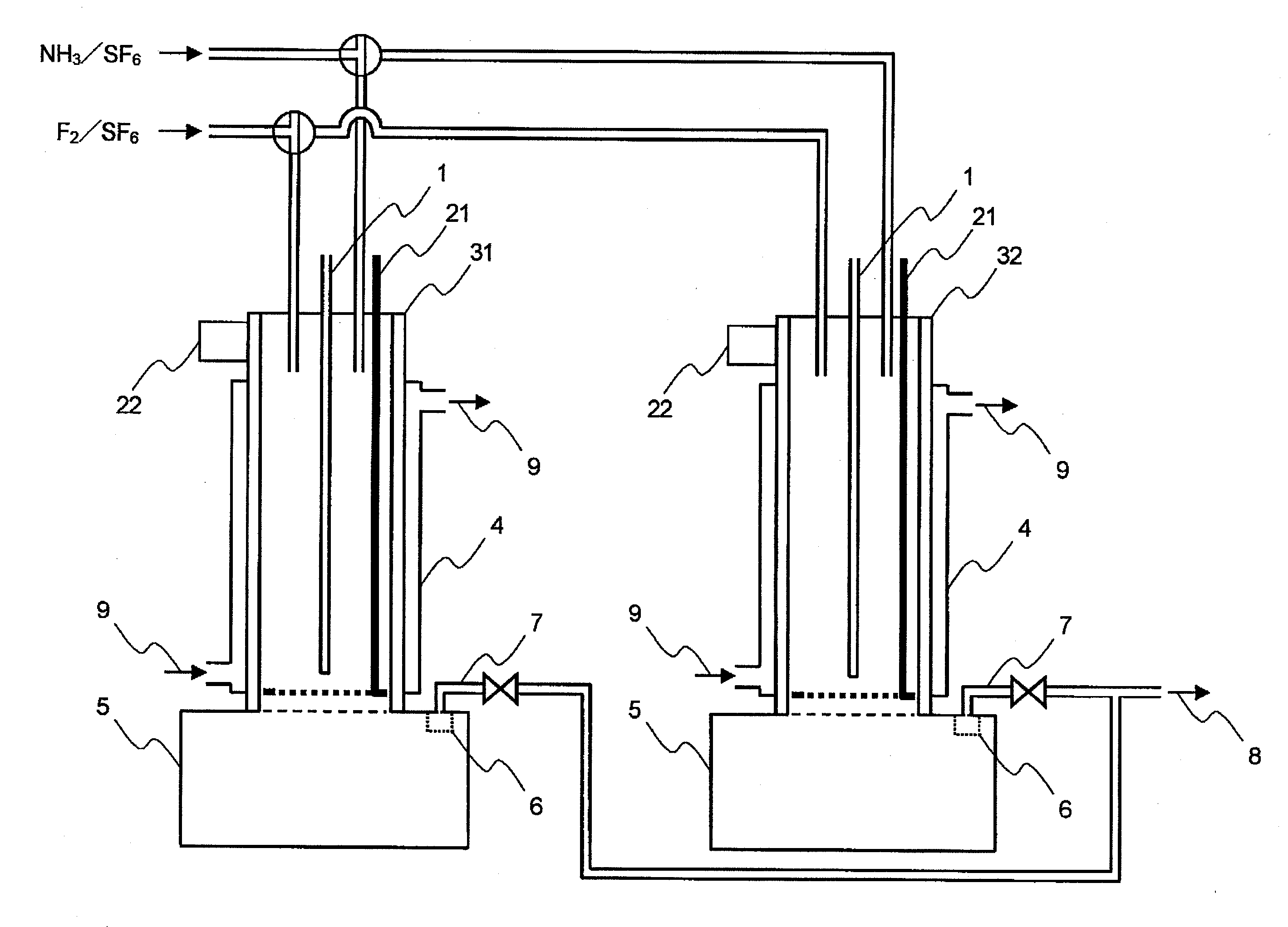
[0060]In another embodiment of the invention, two or more of the tubular reactors are used, and the raw material gases are fed into and reacted in the tubular reactor in a manner such that the two or more tubular reactors are switched alternately. This embodiment preferably involves a device for removing a solid product which is mainly composed of ammonium fluoride and/or acidic am

Problems solved by technology

Since an extremely reactive F2 gas is used in the conventional direct fluorination reactions in which an F2 gas is reacted with NH3 to synthesize NF3, there has been a problem that there is danger of explosion and corrosion.
Further, the temperature inside a reactor increases because these reactions generate a large amount of heat, which fact leads to the decrease of the yield due to the generation of N2, HF, N2F2, N2O, NH4F (ammonium fluoride), NH4HF2 (acidic ammonium fluoride) and the like by side reaction and the decomposition and side reaction of NF3, and which fact also results in the clogging of the reactor and pipes with solids of NH4F and NH4HF2.
Among these problems, Japanese Patent Laid-Open Publication No.
H02-255513 (Patent Document 2) describes that the yield is increased to 59.5% (on the basis of NH3) by using 3 to 20 times as much an F2 gas as an NH3 gas, but the yield is poor on the basis of F2 and this method is not economical.
However, since an expensive F2 gas is used, the problem is to further increase the yield.

Method used


Image

  • Method and apparatus for producing nitrogen trifluoride
  • Method and apparatus for producing nitrogen trifluoride
  • Method and apparatus for producing nitrogen trifluoride

Examples


examples

[0104]Hereinafter, the present invention will be explained by Examples, but the present invention is not limited to these examples.

Examples in which Reactor Equipped with Scraping Device was Used

example a1

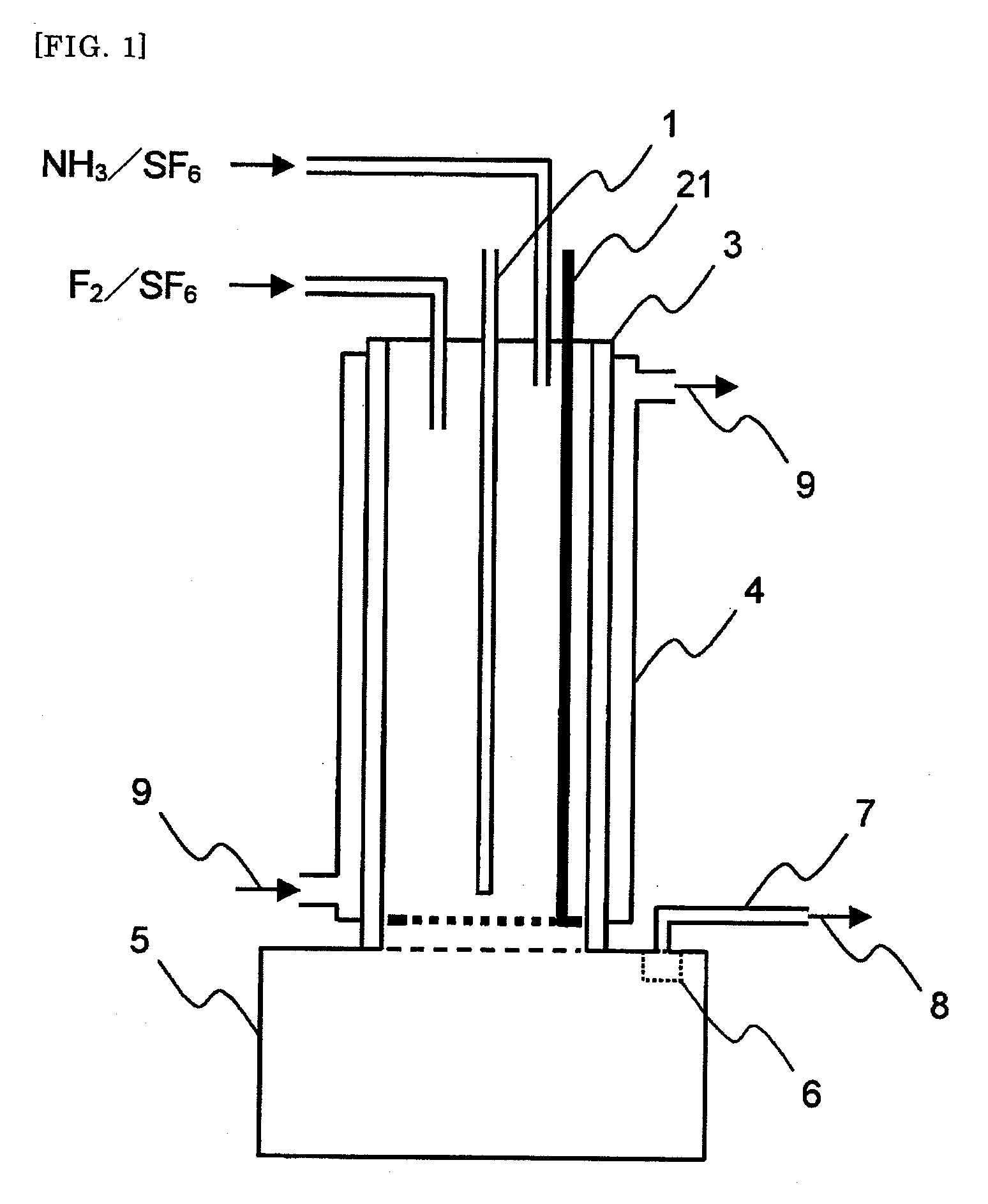
[0105]An apparatus shown in FIG. 1 was used. As shown in FIG. 1, a SUS 316 tubular reactor 3 (with a jacket 4, cooling system with cooling medium circulation) having an internal diameter of 54.9 mm and a length of 480 mm was equipped with two raw material gas feeding lines. In the reactor, an automatically vertically movable scraping device 21 was provided in which a shaft (bar) and a handle were mounted on a ring-shaped thin plate having an external diameter of 53.9 mm and an internal diameter of 53.1 mm. A SUS 316L solid storage tank 5 having an internal diameter of 109.8 mm and a length of 200 mm was mounted at a lower part of the tubular reactor 3. A gas discharge line 7 was connected through a filter 6 to an upper part of the solid storage tank 5.

[0106]Fed in the tubular reactor 3 were a mixed gas of an F2 gas at a rate of 2.3 NL / hr and sulfur hexafluoride at a rate of 59.64 NL / hr from one of the raw material gas feeding lines and a mixed gas of an NH3 gas at a rate of 3.06 NL / ...

example a2

[0120]The reaction was carried out in the same way as in Example A1 except that the reactor 3 was cooled with a cooling medium so that the peak temperature in the reactor 3 was 38.5° C. After 2 hours from the start of the reaction, the gas collected from the gas discharge line was analyzed in the same way as in Example A1. The results are shown below.[0121]F2 reactivity: 94.3%[0122]NF3 yield: 77.4% (on the basis of F2)[0123]HF generation rate: 22.6%

[0124]The comparison of Example A1 with Example A2 showed that the yield of NF3 was further improved by lowering the peak temperature in the reactor.


PUM


Abstract

A method for producing nitrogen trifluoride related to the present invention is characterized in that a fluorine gas and an ammonia gas are fed into a tubular reactor and are reacted with each other in the presence of a diluting gas in a gaseous phase under the condition of no catalyst to produce a gas product mainly composed of nitrogen trifluoride and a solid product mainly composed of ammonium fluoride and / or acidic ammonium fluoride, and then the solid product attached to an inner wall of the tubular reactor is removed by means of a device for removing the solid product, which device is mounted to the tubular reactor.

Description

TECHNICAL FIELD[0001]The present invention relates to a method for effectively producing nitrogen trifluoride (NF3) by reacting a fluorine gas (F2 gas) with an ammonia gas (NH3 gas) in the presence of a diluting gas in a gaseous phase under the condition of no catalyst, and an apparatus used in the method.BACKGROUND ART[0002]NF3 is employed, for example, as a gas for dry etching or a gas for cleaning or the like in a manufacturing process of a semiconductor device. In general, the production methods of this gas are roughly classified into chemical methods and electrolytic methods. Known chemical methods include a method (1) in which F2 gas and NH3 gas are injected into a fused acidic ammonium fluoride (see Japanese Patent Application Publication No. S55-8926 (Patent Document 1)), and a method (2) in which an F2 gas is directly reacted with an NH3 gas (see Japanese Patent Laid-Open Publication No. H02-255513 (Patent Document 2) and Japanese Patent Laid-Open Publication No. H05-105411...

Claims


Application Information

Patent Timeline
IPC IPC(8): C01B21/083B01J19/00
CPCC01C1/162C01B21/0835C01B21/083B01J19/00
Inventor OHNO, HIROMOTOOHI, TOSHIOSAKAI, YUJI
Owner SHOWA DENKO KK
Learn More