Optical Coherence Tomography Laser with Integrated Clock

a coherence tomography and laser technology, applied in semiconductor lasers, instruments, interferometers, etc., can solve the problems of physical size, assembly labor cost, component cost, etc., and achieve the effect of reducing power changes and reducing polarization fading

Active Publication Date: 2009-11-26
EXCELITAS TECH
View PDF17 Cites 108 Cited by
  • Summary
  • Abstract
  • Description
  • Claims
  • Application Information

AI Technical Summary

Benefits of technology

[0024]Preferably, the stress applied to the optical fiber is changed to reduce polarization fading over the scan band of the tunable signal, to reduce changes in power as a function of

Problems solved by technology

The problem with these methods is cost in assemb

Method used


Image

  • Optical Coherence Tomography Laser with Integrated Clock
  • Optical Coherence Tomography Laser with Integrated Clock
  • Optical Coherence Tomography Laser with Integrated Clock

Examples


Embodiment Construction

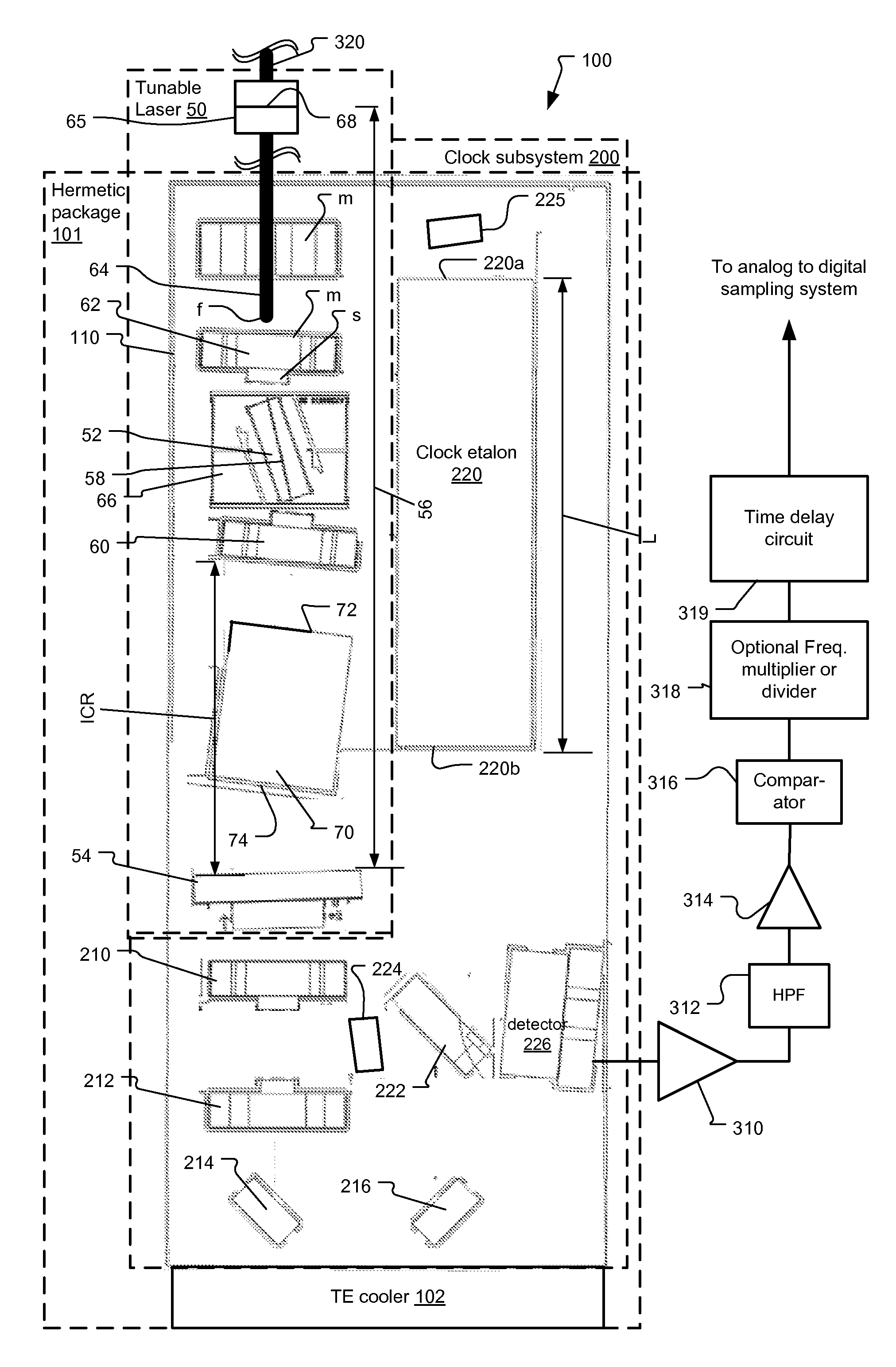
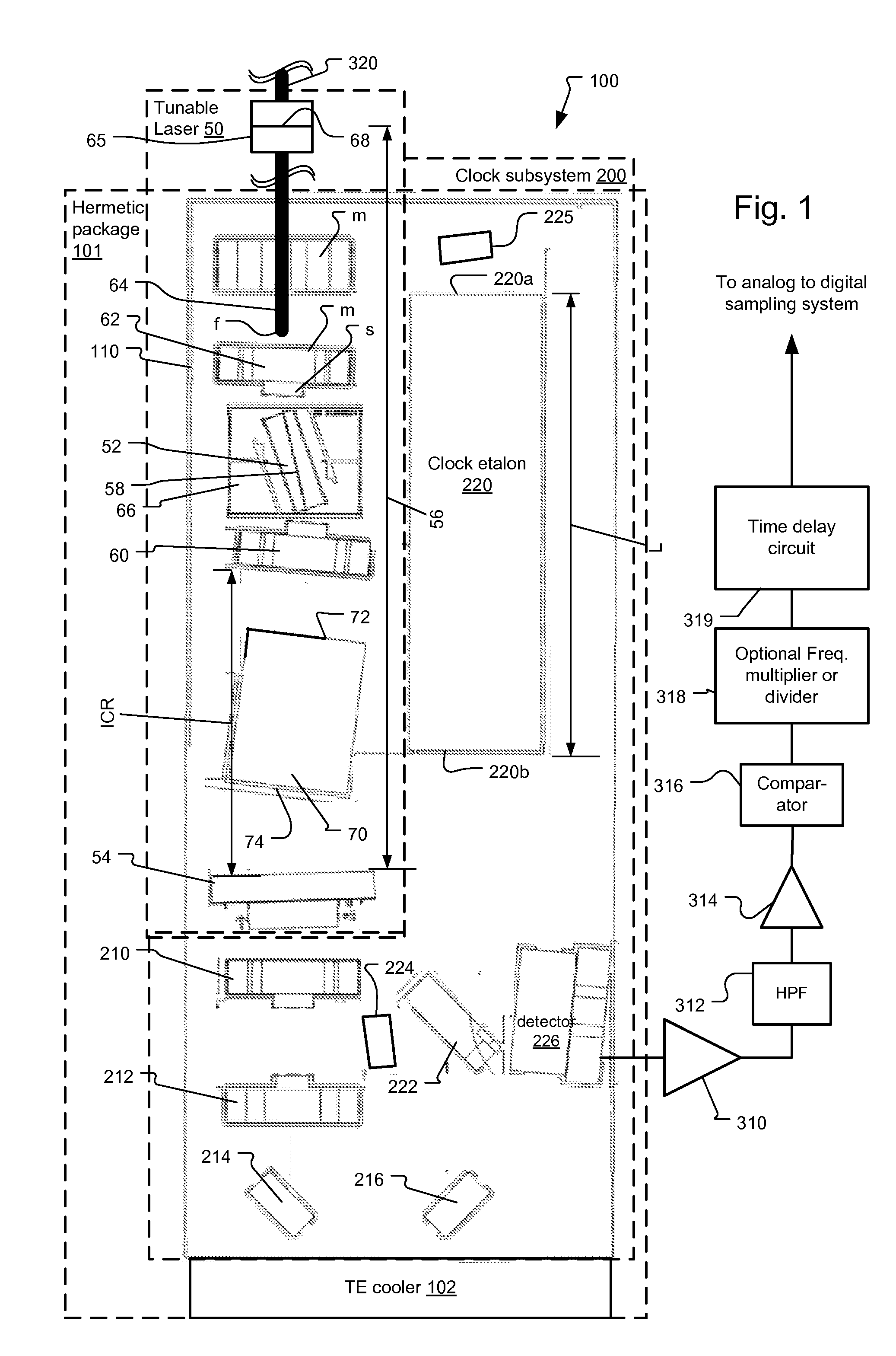
[0034]FIG. 1 shows an integrated laser clock system 100 that has been constructed according to the principals of the present invention.

[0035]Generally the integrated laser clock system 100 comprises a tunable laser subsystem 50, which generates a wavelength or frequency tunable optical signal, and a clock subsystem 200, which generates clock signals at spaced frequency increments as the tunable signals or emissions of the laser 50 are spectrally tuned over a spectral scan band. The clock signals are used to trigger sampling, typically in an OCT system.

[0036]The tunable laser subsystem 50 and clock subsystem 200 of the integrated laser clock system 100 are integrated together on a common optical bench 110. This bench is termed a micro-optical bench and is preferably less than 10 millimeters (mm) by 20 mm in size so that it fits within a standard butterfly or DIP (dual inline pin) hermetic package 101. In one implementation, the bench is fabricated from aluminum nitride. A thermoelect...


PUM


Abstract

A frequency swept laser source for TEFD-OCT imaging includes an integrated clock subsystem on the optical bench with the laser source. The clock subsystem generates frequency clock signals as the optical signal is tuned over the scan band. Preferably the laser source further includes a cavity extender in its optical cavity between a tunable filter and gain medium to increase an optical distance between the tunable filter and the gain medium in order to control the location of laser intensity pattern noise. The laser also include a fiber stub that allows for control over the cavity length while also controlling birefringence in the cavity.

Description

RELATED APPLICATIONS[0001]This application claims the benefit under 35 USC 119(e) of U.S. Provisional Application No. 61 / 053,241, filed on May 15, 2008, which is incorporated herein by reference in its entirety.BACKGROUND OF THE INVENTION[0002]Optical coherence analysis relies on the use of the interference phenomena between a reference wave and an experimental wave or between two parts of an experimental wave to measure distances and thicknesses, and calculate indices of refraction of a sample. Optical Coherence Tomography (OCT) is one example technology that is used to perform usually high-resolution cross sectional imaging. It is often applied to imaging biological tissue structures, for example, on microscopic scales in real time. Optical waves are sent through an object or sample and a computer produces images of cross sections of the object by using information on how the waves are changed.[0003]The original OCT imaging technique was time-domain OCT (TD-OCT), which used a mova...

Claims


Application Information

Patent Timeline
IPC IPC(8): G01B11/02H01S3/10G01D18/00
CPCH01S3/08013H01S3/08054H01S5/02248H01S5/02415H01S5/141G01B2290/25G01B9/02004G01B9/02059G01B9/02044G01B9/02091G01B9/02069H01S5/146H01S5/02325H01S3/1067H01S5/068
Inventor FLANDERS, DALE C.ATIA, WALID A.JOHNSON, BARTLEY C.KUZNETSOV, MARK E.MELENDEZ, CARLOS R.
Owner EXCELITAS TECH
Why Eureka
Try Eureka