Fluidics devices

a technology of fluids and devices, applied in the field of fluids, can solve the problems of ineffective mixing, detrimental bubble problem, lack of effective pumping system, etc., and achieve the effect of reducing or eliminating solutes or analytes

Inactive Publication Date: 2009-11-26
ROCHE MOLECULAR SYST INC
View PDF23 Cites 78 Cited by
  • Summary
  • Abstract
  • Description
  • Claims
  • Application Information

AI Technical Summary

Benefits of technology

[0078]Accordingly, in one aspect the invention provides fluidics devices comprising at least one membranous diaphragm having a first and second side. The first side is for coupling to a pump, and the second side is for fluidic coupling to a flow channel (which can include a detection chamber as a flow channel) and a plurality of check valves. The check valves each comprise a sealing surface comprising a valve seat that allows for regulated flow of fluid through the flow channel and a flexible sealing structure for contacting the valve seat and occluding fluid flow therethrough when in a first position, and for promoting fluid flow therethrough when in a second position. Generally, in this aspect, the diaphragm and the flexible sealing structure are integral to one or more layers of a multilayer assembly (e.g. a multilaminate structure). The plurality of check valves alternate opening and closing in coordinated reciprocal fashion according to alternating positive and negative forces exerted on the diaphragm. In an additional aspect, the device comprises a body comprising a channel (which can be the detection chamber) within for transporting a fluid sample, the channel comprising a situs where an operation is performed on one or more components in the fluid sample. The body also comprises an inlet port for receiving the fluid sample, the inlet port in fluid communication with the channel and also in communication with an enclosed gaseous environment. The inlet port can be configured to receive the fluid sample from a pipette tip, including micropipette tips. The body also comprises an outlet port in fluid communication with the inlet port such that upon operation of the device the fluid sample is recirculated through the channel to release gaseous bubbles into the enclosed gaseous environment while simultaneously allowing for facilitated diffusion and performance of the operation on the one or more components in said fluid sample.
[0087]In an additional aspect, the devices can further comprise caps for sealing the device following the addition of a sample, and optionally a filter, adsorbent and / or absorbent for reducing or eliminating solutes or analytes in the fluid sample.

Problems solved by technology

Collectively they reflect that there is a current and long-felt need for, and past failure of success as relates to, adequate microcassette fabrication and microfluidics, not only from a cost and ease of fabrication and reproducibility standpoint, but also from the standpoint that such systems are typically restricted to laminar flow and feature inefficient mixing compounded by gaseous bubble formation that obstructs or restricts flow and diffusion.
The detrimental problem of bubbles in microfluidic systems is noted repeatedly throughout, as is the general dearth of effective pumping systems in microfluidics systems.
The problem of bubble development is also noted but the vent used is located remote to the inlet and proximal to a waste chamber.

Method used


Image

  • Fluidics devices
  • Fluidics devices
  • Fluidics devices

Examples


example 1

Cartridge Design & Manufacture

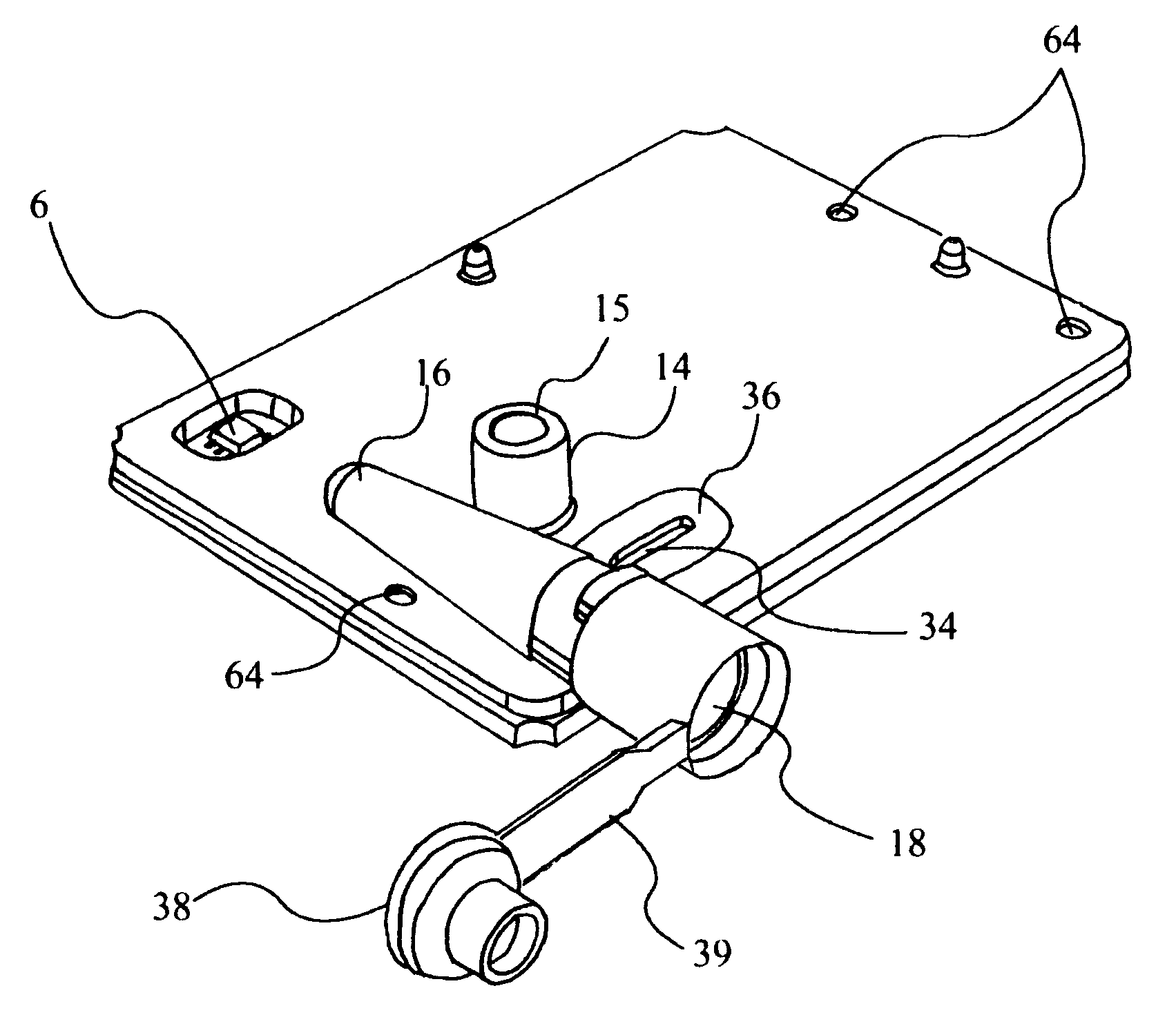
[0226]With reference to FIG. 6, we have chosen a printed circuit board (PCB) (1) to provide the gold surfaces for a 3-electrode electrochemical cell controlled by a potentiostat circuit. It has dual auxiliary electrodes (3) shorted to one another, a multiplicity of working electrodes (4), and a reference electrode (5). The reference electrode is coated with the same electrically conductive silver material (epoxy) that is used to attach an EEPROM (6), and this silver on the reference is electrochemically oxidized immediately prior to analysis to generate the necessary Ag / AgCl redox couple. (While a more standard solder could have been used to attach the EEPROM, this would have introduced additional chemical compounds and manufacturing steps). The PCB geometry lays the working electrodes in 3D wells, which simplifies the process of applying differing chemical treatments to each electrode to create the desired capture surfaces.

[0227]In embodiment, the cart...

example 2

Cartridge Module Design & Manufacture

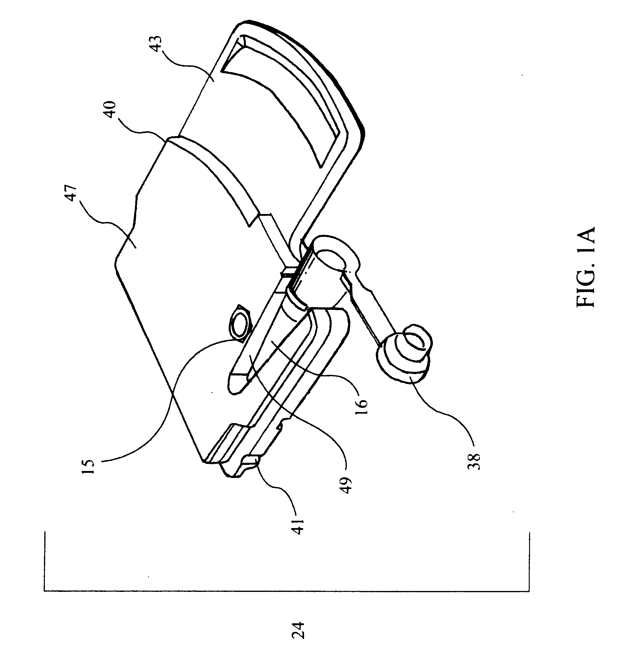
[0241]With reference to FIGS. 13A-E, the interface between detection device (23) and cartridge (24) is mediated by a cartridge module (42), which consists of a base (50) and top (51), both of which are made of molded polyetherimide plastic (glass-filled Ultem®, General Electric), and both of which contain aligned embedded metal screw castings (52) for fastening to each other. Module top (51) contains a connector lever (53) and engagement plate (54) for slideably engaging and disengaging cartridge firmly against base (50) and buckle beam assembly (73) electrical connection points therein. Top (51) also contains a conduit (55) for mating with the cartridge chimney (14) and feeding and withdrawing air to and from said cartridge. Base (50) has a heater area (56) for receiving and mating with a gold / nickel plated copper thermal plate (57) and buckle beam assembly (73) that consists of an array of gold / nickel plated beryllium copper pins parallel and p...

example 3

Detection Device

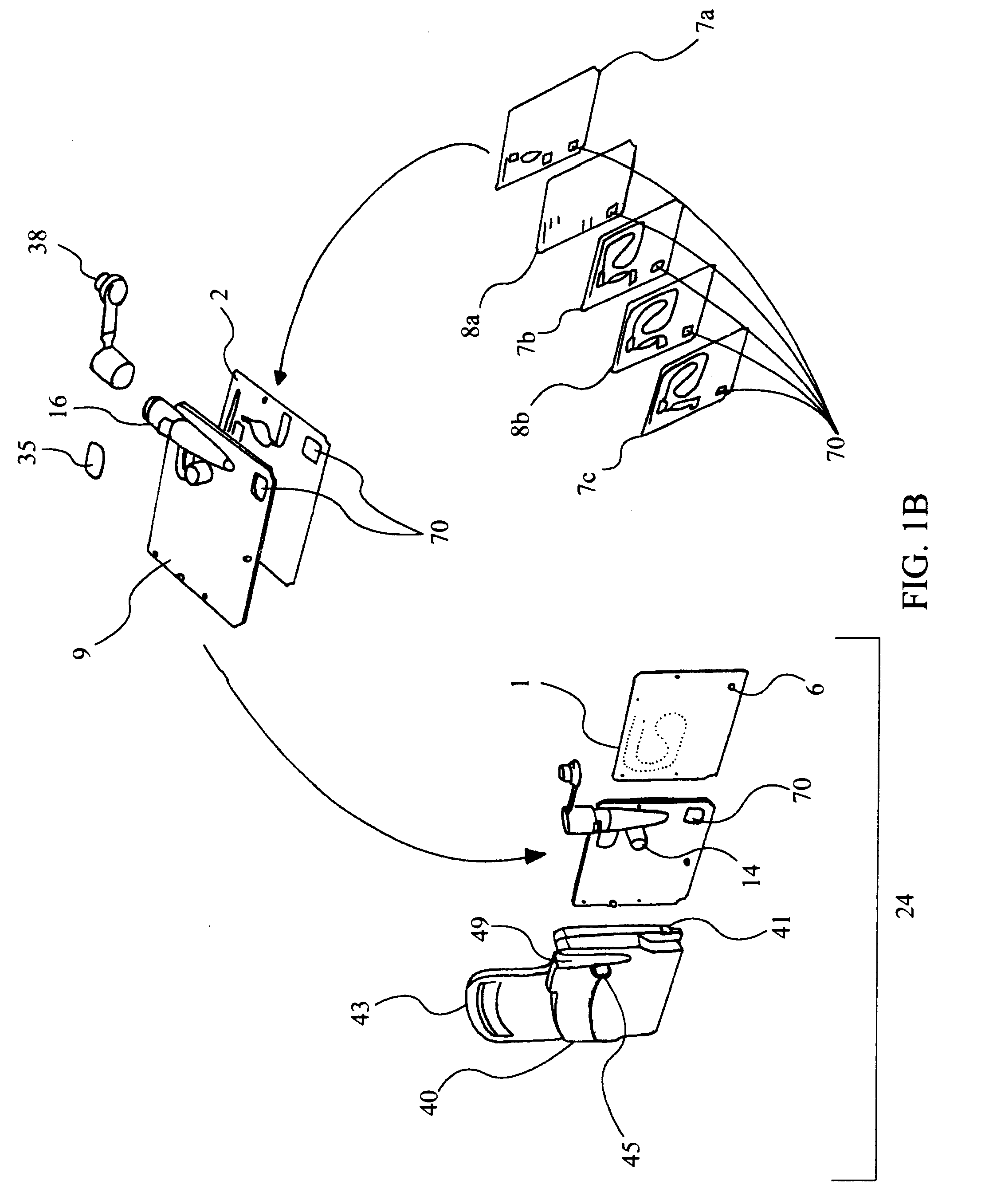
[0244]In typical use, and with reference to FIG. 14, the cartridge and cartridge module are coupled to a detection device (23) and / or computer, which parts may be combined into one, as is known and readily implementable in the art. FIG. 14 shows an embodiment of a detection device (23) for housing multiple cartridges (24). This embodiment contains three vertical towers (65) each possessing eight cartridges (24), each of which fits into its own module (42). To the left is a computer screen (66) for programming detection parameters and evaluating results. In this particular embodiment the screen is a touch-pad screen from which a user may conveniently select from various programming options merely by touching the screen. The fill reservoir / chambers (16) of the cartridges (24) face out at an approximate 15° angle relative to horizontal to take advantage of gravity and 3-dimensional space to economize / optimize onlooker or technician view and facilitate loading / clamping o...


PUM

PropertyMeasurementUnit
heightaaaaaaaaaa
widthaaaaaaaaaa
lengthaaaaaaaaaa

Abstract

The invention relates to fluidics as used in medical and diagnostic equipment and relates further to means for purifying, abstracting, filtering, detecting and / or measuring analytes in liquid samples.

Description

RELATED APPLICATIONS[0001]This application is a divisional of U.S. patent application Ser. No. 12 / 032,356, filed Feb. 15, 2008, entitled the same, and claims the benefit of U.S. Provisional Patent Applications Nos. 60 / 890,180, filed Feb. 15, 2007, and 60 / 953,197, filed Jul. 31, 2007, entitled the same, all of which are incorporated by reference.FIELD OF THE INVENTION[0002]The invention relates to fluidics as used in medical and diagnostic equipment and relates further to means for purifying, abstracting, filtering, detecting and / or measuring analytes in liquid samples.BACKGROUND OF THE INVENTION[0003]The following documents are all incorporated herein by reference in their entireties, although none is admitted to be prior or relevant art. Collectively they reflect that there is a current and long-felt need for, and past failure of success as relates to, adequate microcassette fabrication and microfluidics, not only from a cost and ease of fabrication and reproducibility standpoint, ...

Claims


Application Information

Patent Timeline
Patent Type & Authority Applications(United States)
IPC IPC(8): G01N33/53B01L3/00
CPCB01L3/502707G01N27/27B01L3/502723B01L3/502738B01L7/52B01L7/525B01L9/527B01L2200/025B01L2200/027B01L2200/0684B01L2200/10B01L2300/023B01L2300/024B01L2300/0636B01L2300/0645B01L2300/0816B01L2300/0867B01L2300/0874B01L2300/088B01L2300/0887B01L2300/123B01L2300/1827B01L2400/0439B01L2400/0442B01L2400/0478B01L2400/0481B01L2400/0487B01L2400/0605B01L2400/0655B01L3/502715
Inventor CLEMMENS, CHARLES E.MUCIC, ROBERTMONTALVO, RUDOLPH A.FOSTER, CLARKGUST, GARY R.ROBINSON, THOMAS P.OLSEN, GARY T.
Owner ROCHE MOLECULAR SYST INC
Why Eureka
Try Eureka