Charged particle beam apparatus

a technology of chargeable particles and beams, applied in the field of chargeable particle beam apparatuses, can solve the problems of adverse effect of reducing emission current, difficult to effectively achieve evacuation in the vicinity of electron sources, and possible adverse effects of emission current reduction

Active Publication Date: 2009-12-03
HITACHI HIGH-TECH CORP
View PDF5 Cites 18 Cited by
  • Summary
  • Abstract
  • Description
  • Claims
  • Application Information

AI Technical Summary

Benefits of technology

[0026]With the present invention, the degree of vacuum in the vicinity of the charged particle source can be kept to the ultra-high vacuum such as 10−8 to 10−9 Pa and thus the charged particle beam apparatus without problems due to foreign particles and the vacuum starting method can be provided.

Problems solved by technology

However, the electron source kept in a ultra high degree of vacuum is installed in a narrow region surrounded by the electrode to generate field for extracting and if a small amount of gas is emitted in the vicinity of the electron source, the degree of vacuum inside the electron gun chamber is maintained but the pressure in the vicinity of the electrode of the electron source is suddenly increased, such that an adverse effect may occur.
In particular, in the case of thermal field emitter electron source (Schottky electron source), as described in Journal of Vacuum Science Technology, Vol. 12, No. 6, 1975; L. W. Swanson; “Comparative study of the zirconiated and built-up W thermal-field cathode,” it has been known to cause an adverse effect of decreasing the emission current when there is a very small amount of oxygen.
In the case where only the ion pump is used for the vacuum evacuation, since there are an electrode, a magnetic shield, etc. between the electron source and the ion pump and the conductance is lowered, there is a problem in that it is difficult to effectively achieve evacuation in the vicinity of the electron source.
On the other hand, in the case of using the non-evaporable getter pump, there are other problems.
For microscopic concave-convex shape, there is a high probability that the point becomes fragile and drops out.
Since the non-evaporable getter alloy has conductive property, if it falls into the electron optical system where there are electrodes applied with a high voltage, it causes problems such as discharge, a short, etc.
Another problem in using the non-evaporable getter pump is that there is a relationship between a temperature (activation temperature) to activate the non-evaporable getter alloy and a baking temperature to heat the vacuum vessel when the vacuum starts.
If the activation temperature selected lower than baking temperature or less in the evacuation procedure, the activation is progressed during the baking and a massive amount of gas generated by the baking is absorbed during the baking, which causes a problem in that the pumping speed decreases or the lifetime of the pump is shortened.

Method used


Image

  • Charged particle beam apparatus
  • Charged particle beam apparatus
  • Charged particle beam apparatus

Examples


first embodiment

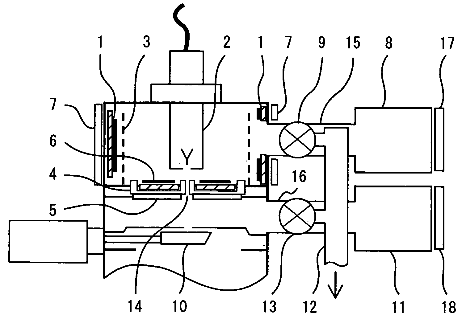
[0038]FIG. 1 shows a configuration of a charged particle beam generator according to a first embodiment using an electron gun. Hereinafter, the electron gun according to the first embodiment will be described in detail.

[0039]A vacuum chamber, which is a vacuum vessel, includes an electron source 2 to emit electrons downward. The emitted electron beam passes through an aperture 14 and enters into a sample via an electron optical system installed below the aperture 14. The inside of the electron gun has a differential pumping system from which the aperture is separated and includes vacuum pumps, respectively, to evacuate each chamber. In the first embodiment, the charged particle beam generator, that is, the electron gun means a configuration that the electron gun is positioned at a higher portion than a movable valve 10.

[0040]The vacuum chamber in which the electron source 2 is disposed is coupled with a vacuum pump 8, a valve 9, and a rough pumping port (rough pumping hole) 12 via a...

second embodiment

[0056]In a second embodiment, a case where the electron gun described in the first embodiment is applied to the scanning electron microscope will be described. FIG. 6 is a schematic configuration diagram of the scanning electron microscope (SEM). The electron gun as the charged particle beam generator shown in FIG. 1 is mounted on the top. An electron optical system 28, an objective lens 31, and a sample chamber 35 are disposed on the lower portion of the electron gun in series and are separated each other by the aperture for passing through the electron beam 36. The vacuum evacuation of the electron optical system chamber 28 includes a dedicated vacuum pump 26 similar to the electron gun. For the vacuum evacuation from the atmosphere, each chamber is connected to the rough pumping port 12 and can be opened and closed by the valve 30 for rough pumping. The rough pumping port 12 is connected to the sample chamber 35 and the vacuum evacuation of the sample chamber 35 is performed by a...

third embodiment

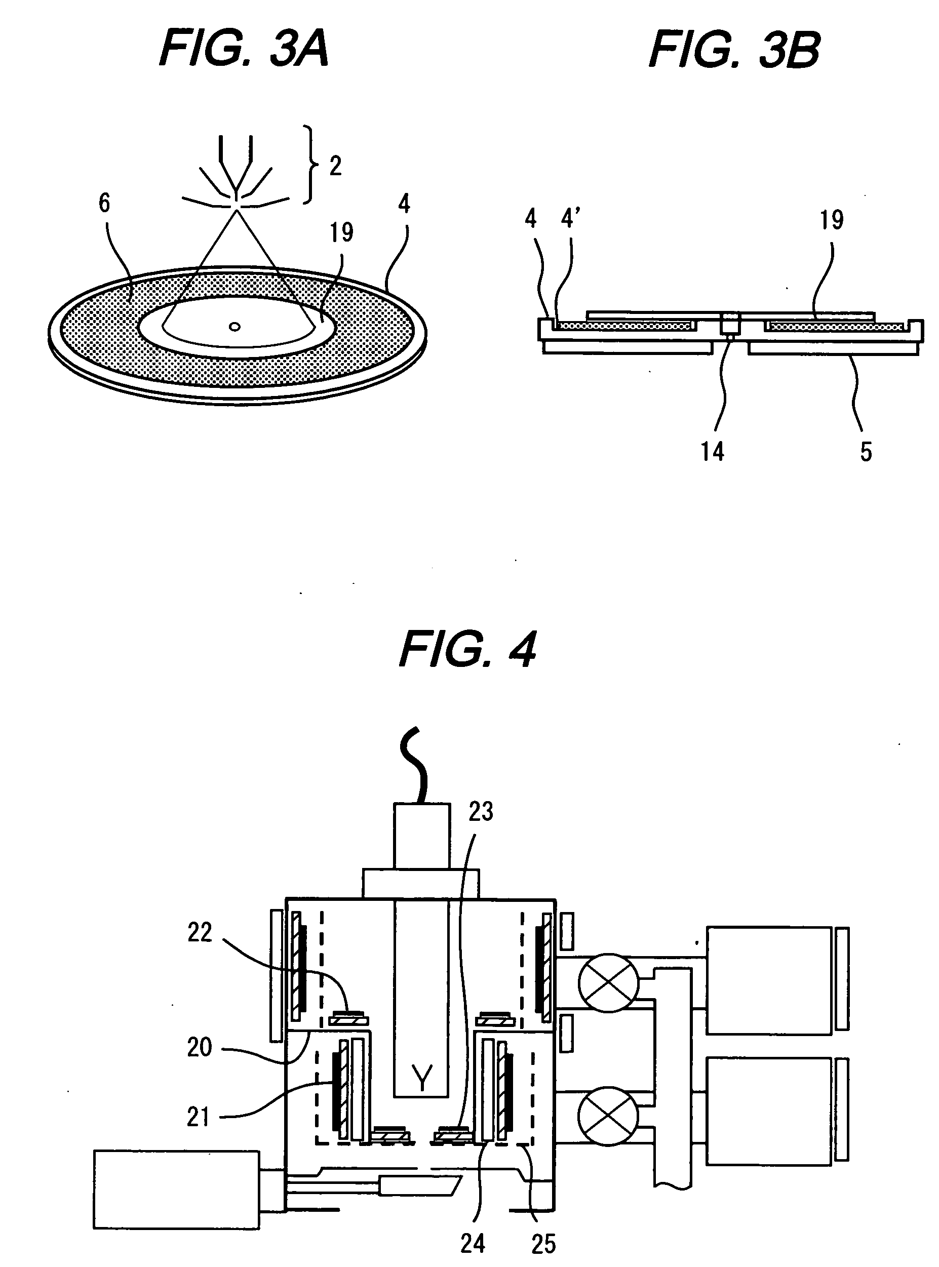
[0061]A configuration of a third embodiment where the charged particle beam generator having a separate configuration is applied to the scanning electron microscope apparatus will be described with reference to FIG. 7.

[0062]An electron gun according to the third embodiment has a structure including a non-evaporable getter pump 36 having a high pumping speed in addition to the vacuum pump 11 that evacuates the vacuum chamber 39 that is located lower side of the vacuum chamber 38 in which the electron source 2 exists. Theses two chambers are separated each other by the aperture.

[0063]In the scanning electron microscope, in the case of observing the images as shown in FIG. 7, since the scanning electron microscope is connected to the sample chamber having the lowest degree of vacuum by the aperture through which the electron beams passes, there is a problem. The problem is an increased possibility that the gas in the sample chamber could blow up in the vicinity of the electron source 2...


PUM


Abstract

The present invention provides a charged particle beam apparatus that keeps the degree of vacuum in the vicinity of the electron source to ultra-high vacuum such as 10−8 to 10−9 Pa even in the state where electron beams are emitted using a non-evaporable getter pump and is not affected by dropout foreign particles.
The present invention includes a vacuum vessel in which a charged particle source (electron source, ion source, etc.) is disposed and a non-evaporable getter pump disposed at a position that does not directly face electron beams and includes a structure that makes the non-evaporable getter pump upward with respect to a horizontal direction to drop out foreign particles into a bottom in a groove, so that the foreign particles dropped out from the non-evaporable getter pump do not face an electron optical system. Or, the present invention includes a structure that is covered by a shield means, or a means that is disposed immediately on a surface of the non-evaporable getter pump but at a position where the electron beams are not seen and has a concave structure capable of trapping the dropout foreign particles on a lower portion of the non-evaporable getter pump.

Description

CLAIM OF PRIORITY[0001]The present application claims priority from Japanese patent applications JP2008-139473 filed on May 28, 2008, and, JP2009-103490 filed on Apr. 22, 2009, the content of which is hereby incorporated by reference into this application.BACKGROUND OF THE INVENTION[0002]1. Field of the Invention[0003]The present invention relates to a charged particle beam apparatus, such as an electron microscope, an electron beam writer, a focused ion beam system, etc. and in particular, to an evacuating technology that can achieve extremely high degree of vacuum of an electron gun or an ion gun.[0004]2. Description of the Related Art[0005]A scanning electron microscope (SEM) or an electron beam writer (EB) according to the related art accelerates electron beams emitted from an electron gun including a cold cathode field emission type electron source or a thermal field emitter electron source, which are changed into fine electron beams using an electron lens, and scans them as pr...

Claims


Application Information

Patent Timeline
Patent Type & Authority Applications(United States)
IPC IPC(8): A61N5/00G21F5/02
CPCH01J2237/188H01J2237/182H01J2237/06341H01J37/18
Inventor KATAGIRI, SOUICHIOHSHIMA, TAKASHITAKAMI, SHOEZUMI, MAKOTODOI, TAKASHIKASAI, YUJI
Owner HITACHI HIGH-TECH CORP
Why Eureka
Try Eureka