Real Time Detection of Molecules, Cells and Particles Using Photonic Bandgap Structures

a photonic bandgap and real-time detection technology, applied in the field of molecular biology, biochemistry, genomics, nanotechnology and analytical chemistry, can solve the problems of limiting the widespread use of photonic bandgap sensors, high cost of complex instruments, and inability to meet the needs of specific applications

Inactive Publication Date: 2009-12-10
BEATTIE KENNETH L +1
View PDF2 Cites 5 Cited by
  • Summary
  • Abstract
  • Description
  • Claims
  • Application Information

AI Technical Summary

Benefits of technology

[0009]The present invention is directed to a a photonic bandgap (PBG) detector. The PBG detector comprises one or more photonic crystals having a matrix structure defining a plurality of channels having a length I therethrough, a fluid within the channel(s) and flowable therethrough and means for biochemically inducing a detectable increase in light transmission within a bandgap region of the photonic crystal. The PBG detector also comprises means for transmitting light within the bandgap region and means for detecting the increase in light transmission therein. A related PBG detector further comprises an optical filter operably disposed between the photonic crystal and the means for detecting the increase in light transmission. Another related PBG detector further comprises means for applying a variable back pressure to the flow through the channels.

Problems solved by technology

However, current miniaturized binding assays, including both DNA and protein microarrays, suffer from several limitations which impede their widespread use and make certain applications impossible.
Included are the requirement to introduce a label into the target analyte in order to enable detection and quantification, the need to analyze relatively large samples, requirement to provide target or signal amplification to enable detection of low quantities of analyte, and high cost of complex instrumentation.
“Label-free” analytical instruments are available, employing surface plasmon resonance (SPR) sensors, but these are expensive and require relatively high concentrations of analyte.
Detection sensitivity is a critical issue, particularly with small sample volumes.
The current detection limit of DNA and protein array devices is typically hundreds to thousands of target molecules.
Although this level of sensitivity is adequate for some types of samples, it is a prohibitive limiting factor for minute sample volumes (nanoliter to picoliter range), or for larger samples (milliliter to microliter range) containing very small numbers of target molecules.
There is currently no device which can approach single molecule detection over a wide range of sample volumes.
Specifically, the prior art is deficient in simpler and more cost effective analytical devices that approach single molecule detection sensitivity over a wide range of sample volumes without labeling the analyte or amplifying the target or signal.
More specifically, the prior art is deficient in the real-time simultaneous detection of a multiplicity of binding reactions using photonic bandgap structures.

Method used


Image

  • Real Time Detection of Molecules, Cells and Particles Using Photonic Bandgap Structures
  • Real Time Detection of Molecules, Cells and Particles Using Photonic Bandgap Structures
  • Real Time Detection of Molecules, Cells and Particles Using Photonic Bandgap Structures

Examples


example 1

Real Time Detection of Cells Using Photonic Bandgap Structures

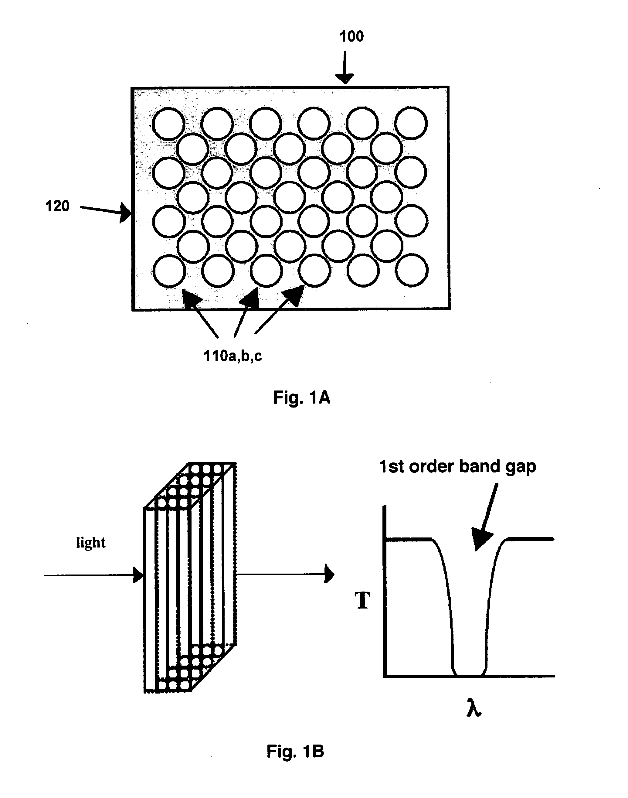
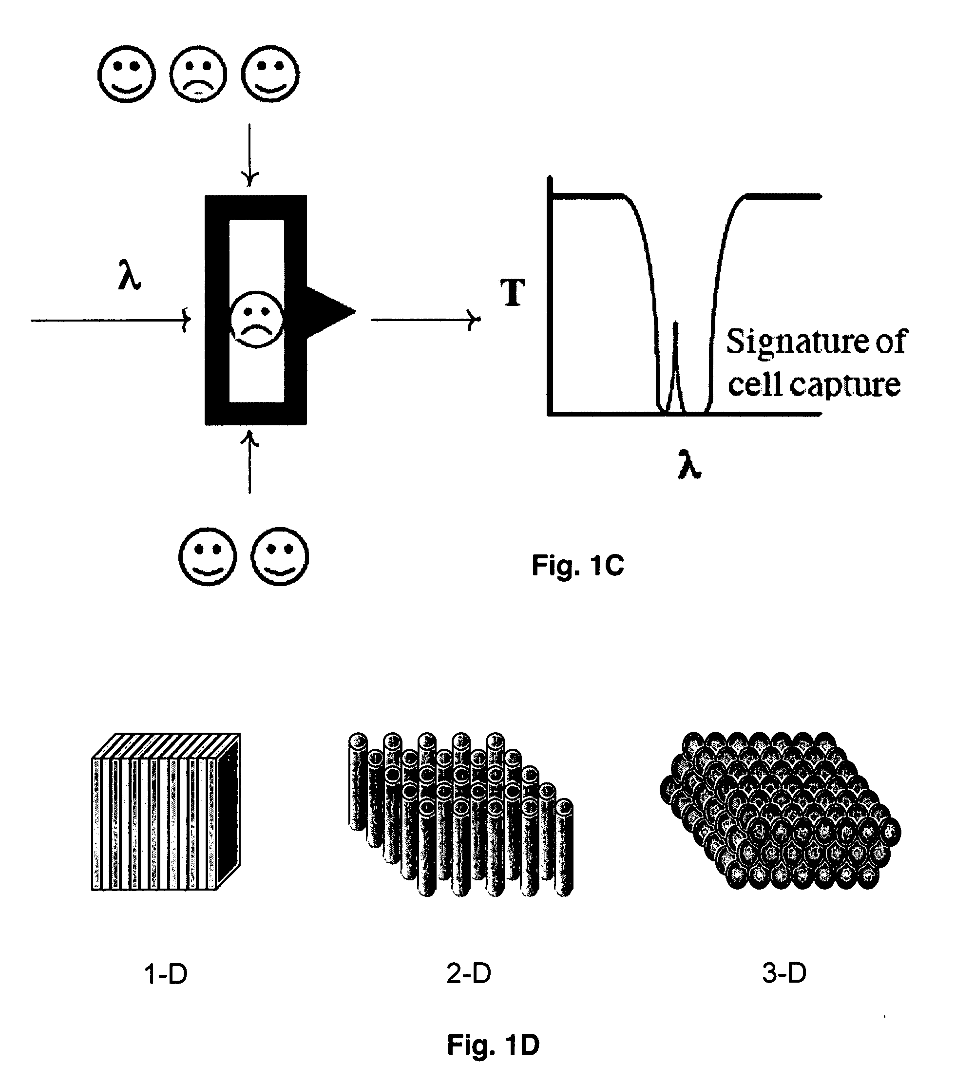
[0049]The observation of photonic crystal defects optically depends upon the orientation of the photonic crystal and the direction of observation. For the devices described in these Examples, detection of defect structures is either along an axis of high symmetry, exhibiting the simplest band structure or vertically, perpendicular to a high symmetry axis for high throughput devices. The operation of a 2-dimensional PBG structure to detect a cell, such as a bacterium or lymphocyte is shown in FIGS. 1A-1C. FIG. 1D shows various possible geometries, i.e., 1-, 2- and 3-dimensional, of PBG structures.

[0050]FIG. 1A shows a 2-dimensional hexagonal close packed structure 100 containing uniform holes 110a,b,c or channels in a dielectric matrix 120. The dielectric medium is considered transparent in the region of interest. The holes represent approximately 40 percent open area for the region containing them. Such a structure would ...

example 2

Real Time Detection of Spherical or Cyllindrical Particles Using Photonic Bandgap Structures

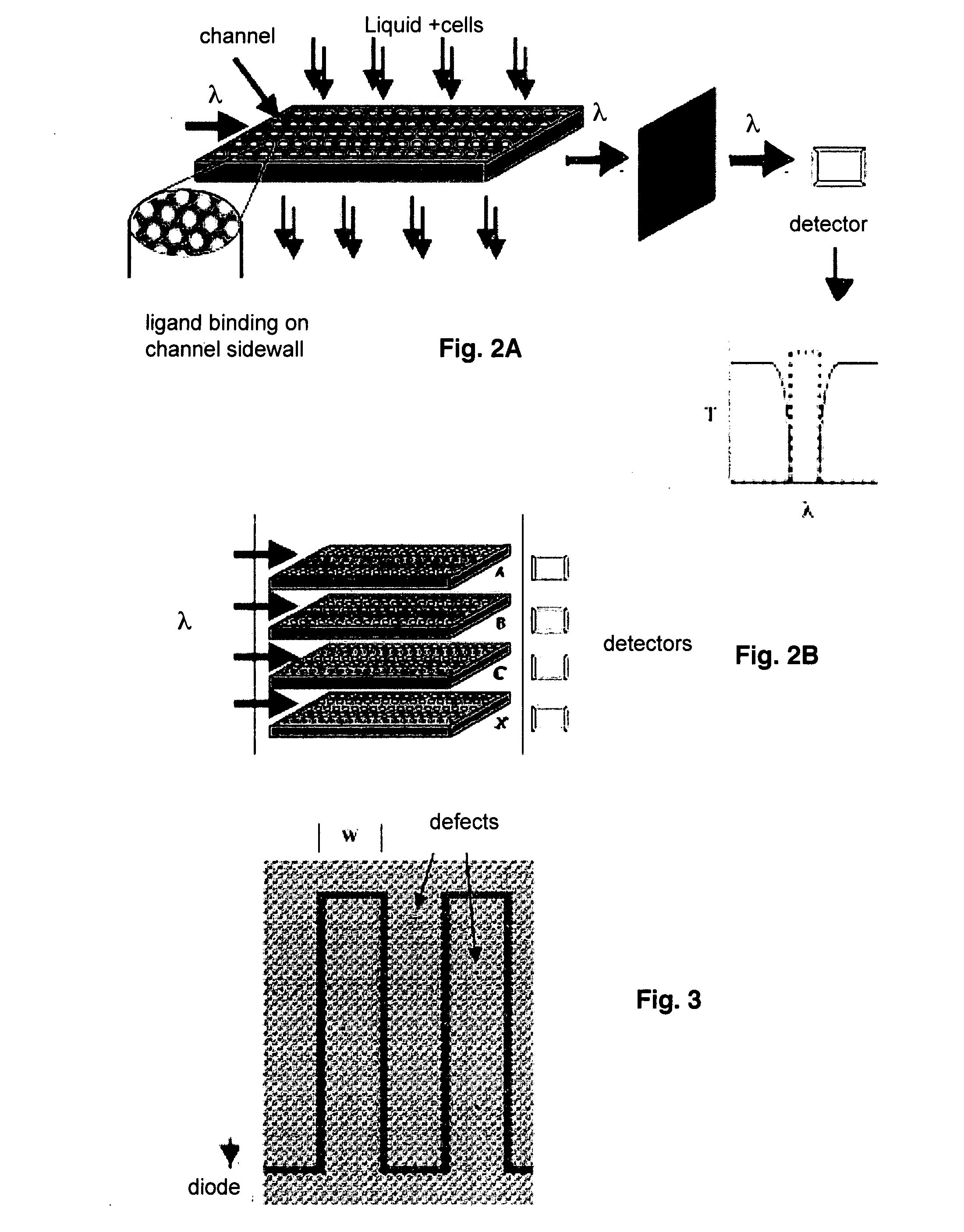
[0063]If the rod in Example 1 were replaced by a sphere of diameter slightly smaller than that of the channels of the PBG structure, a similar transmission of light is induced within the band gap while the sphere resides within the PBG structure. For this example it is assumed that the length of the channel is also on the same order as the diameter of the channel. The side walls of the PBG channels and spheres may be chemically modified to provide a thin coating of specific binding reagents. The specific binding reaction causes a particular surface modified sphere to stick to the side wall of the channel as it passes through the PBG structure preventing the sphere from moving out of the channel. As in Example 1, a photo detector may be utilized to detect capture of a sphere within the PBG structure indicating a binding reaction has taken place. Spheres lacking the specific chemical modificati...

example 3

[0064]Use of “Reporter Particles” to Detect Smaller Objects or Substances

[0065]The binding reaction between the surface of the channel and a spherical or cylindrical particle in Example 2 may be modified to provide a particularly useful embodiment of the PBG sensor device, in which a “reporter particle” is provided which functions to detect much smaller substances. The side walls of the PBG channels are chemically modified with a thin reactive coating of type A and the surface of the spherical or cylindrical “reporter particle” is chemically modified by a thin reactive coating of type B. The coatings A and B are selected to be nonreactive, i.e., do not bind, to each other, but so bind specifically to separate sites on a third molecule, cell, particle or other substance of interest, e.g., the analyte, whose dimensions are small compared to the channel and reporter particle diameters.

[0066]If a reporter particle coated with reagent B is introduced into the PBG structure, it will pass ...


PUM

PropertyMeasurementUnit
lengthaaaaaaaaaa
diameteraaaaaaaaaa
diameteraaaaaaaaaa

Abstract

Provided herein is a photonic bandgap (PBG) detector effective to detect inorganic molecules, organic biomolecules or biopolymers, cells, subcellular organelles, and particles. The PBG detector utilizes photonic crystals having a binding agent attached to channel surfaces comprising the crystals to selectively bind a molecule, cell or particle of interest so that an increase in light transmission is detectably induced within the photonic bandgap upon binding. Also provided are methods of optically detectiing an analyte and of identifying the presence of a cell or a particle in a biological sample.

Description

BACKGROUND OF THE INVENTION[0001]1. Field of the Invention[0002]The present invention relates generally to the fields of molecular biology, biochemistry, genomics, proteomics, nanotechnology and analytical chemistry. More specifically, the present invention relates to a novel photonic bandgap sensor device for real time detection of inorganic, organic or biological substances.[0003]2. Description of the Related Art[0004]Micro- and nanoscale fabrication processes are revolutionizing the electronics and biomedical fields, enabling miniaturized analytical instrumentation for numerous industrial and medical applications. The impact of micro- and nanofabrication technology in biomedical research can be seen in the increasing presence of miniaturized analytical instrumentation in research and clinical laboratories. The emergence of “lab-on-a-chip” and similar automated small-scale instruments is expected to benefit the fields of genomics, proteomics, metabolomics, medical and environmenta...

Claims


Application Information

Patent Timeline
Patent Type & Authority Applications(United States)
IPC IPC(8): C12Q1/70G02B6/00C12Q1/68G01N33/53G01N33/567C12Q1/02C12M1/34G01N21/00
CPCG01N21/05G01N21/77G01N2021/0346G01N2021/7783G01N33/54373Y02A50/30
Inventor BEATTIE, KENNETH L.TONUCCI, RONALD J.
Owner BEATTIE KENNETH L
Why Eureka
Try Eureka