Implantable neural prosthetic device and methods of use

a neural prosthetic and implantable technology, applied in the field of implantable neural prosthetic devices and methods of use, can solve the problems of device being slowly pushed out of position in the tissue, and affecting the patient's comfor

Inactive Publication Date: 2009-12-10
CENT NERVOUS SYST
View PDF0 Cites 102 Cited by
  • Summary
  • Abstract
  • Description
  • Claims
  • Application Information

AI Technical Summary

Problems solved by technology

However, when the electrodes are implanted intrusively, nervous tissue (and in some cases the actual hardware implanted) is often damaged.
Intrusive implantation of electrodes also increases the risk of infection to the patient.
Additionally, long term intrusive implantation of such devices can result in encapsulation of the device by fibrous tissue, otherwise known as gliosis, resulting in the device being slowly pushed out of position in the tissue.
The insertion of electrodes can additionally cause pressure in the nervous tissue at the implantation site.
Encapsulation of the device can lead to a drop in performance and can ultimately lead to further complications if the device is implanted for longer periods of time.
Finally, surgery costs for intrusive implantation are very high.
However, due to the placement on the surface of the skin, non-intrusive electrodes generate a poor quality signal due to interference and noise caused by the presence of tissue between the nerves and the sensors placed at the surface of the skin.
As a result, non-intrusive electrodes are computationally intensive, while giving only low data extraction rates.
Another drawback to the non-intrusive method is that electrodes may need to be systematically reapplied to the skin of the patient each time the patient wishes to interface with the system.
Such replacement processes can take up to 60 minutes to perform.
While this technique represents a new approach to detecting electrical signals, this method still uses basic detection technology and hence has performance limitations as well as several disadvantages, such as the extensive amount of surgery required and a low amount of viable applications.
For example, spinal cord injuries cannot be addressed by this method.
Furthermore, detecting from the brain is computationally intensive.
However, peripheral methods cannot be used for individuals suffering from spinal cord injury or peripheral neuropathy for example.
Additionally, implants placed in the peripheral nervous tissue are susceptible to movement due to motion from nearby muscle groups and can thereby damage nervous tissue if implanted intrusively or become misaligned if non-intrusive.

Method used


Image

  • Implantable neural prosthetic device and methods of use
  • Implantable neural prosthetic device and methods of use
  • Implantable neural prosthetic device and methods of use

Examples


Embodiment Construction

[0030]The invention provided herein comprises for a device for detecting the electrical activity of neural tissue. In some aspects, the device is capable of stimulating, modulating and suppressing neural tissue.

[0031]The spinal cord is a collection of neurons that travels within the vertebral column and is an extension of the central nervous system. Within the spinal cord is grey matter surrounded by white matter. The spinal cord extends from the brain and is enclosed in and protected by the bony vertebral column. In detecting neural activity from the spinal cord, and stimulating neural tissue, conventional methods suffer the drawback of either needing invasive surgery to implant the neural device or lack of sensitivity of the device.

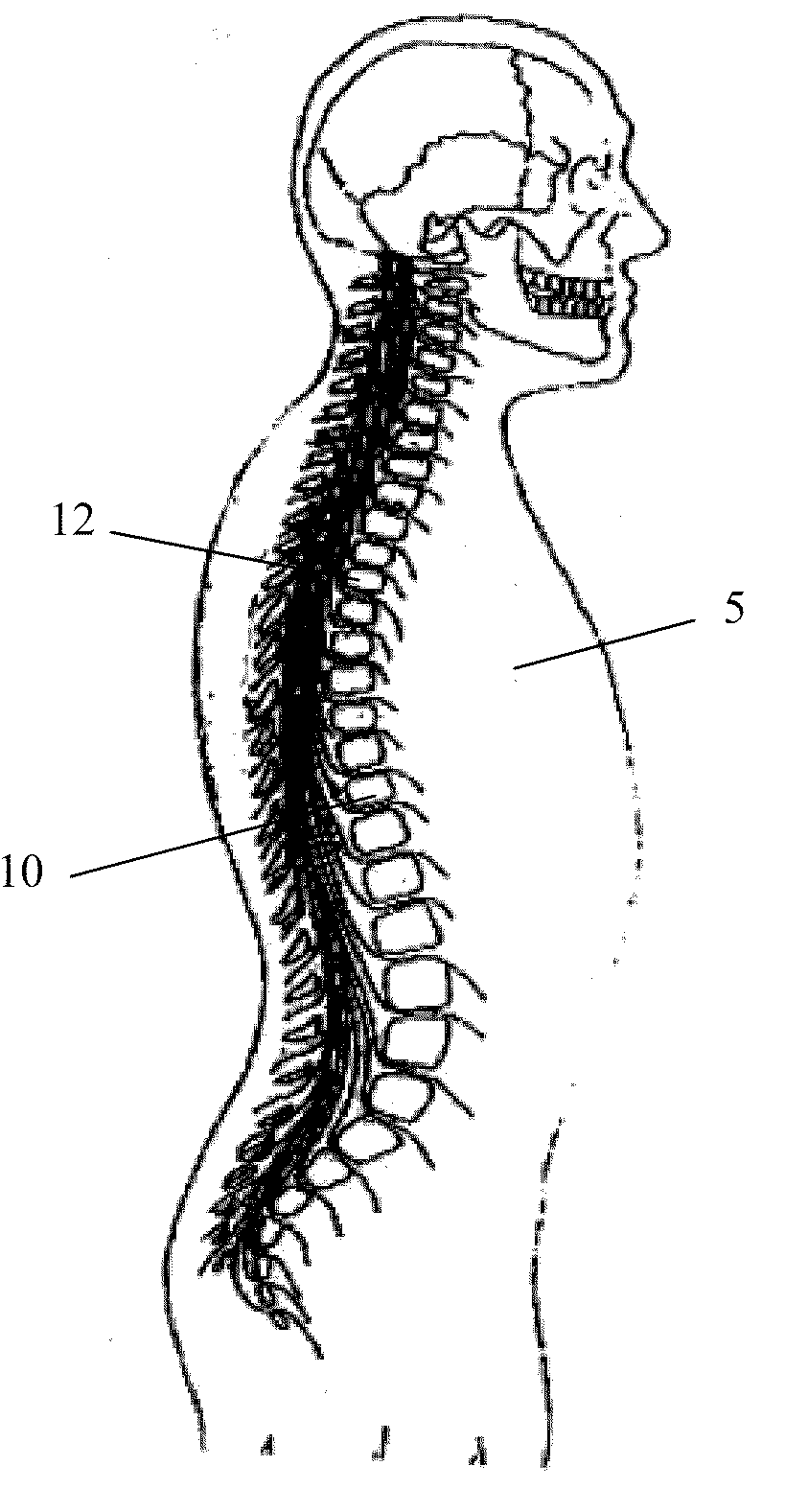
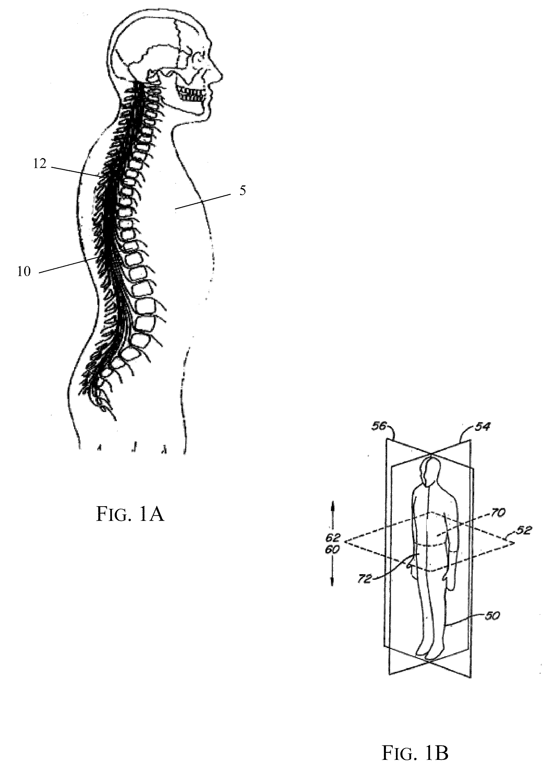
[0032]A body cavity 5 with spinal column is shown in FIG. 1A. The devices of the invention are designed to interact with the human spinal column 10, as shown in FIG. 1A, which comprises of a series of thirty-three stacked vertebrae 12 divided into five ...


PUM


Abstract

Neural stimulation devices are described that detect the neural activity from the spinal cord in a semi-invasive manner, where the device comprises at least one antenna array comprising an antenna. The antenna of the array is in electrical communication with the spinal cord of the patient. A device comprising more than one antenna array can be used to detect the neural signal strength, as well as the velocity and directionality of the signal.

Description

CROSS-REFERENCE[0001]This application claims the benefit of U.S. Provisional Application No. 61 / 057,266, filed May 30, 2008 and entitled “IMPLANTABLE NEURAL PROSTHETIC DEVICE AND METHODS OF USE,” which application is incorporated herein by reference.BACKGROUND OF THE INVENTION[0002]Neural prosthetic devices detect the electrical activity of the nervous system in order to extract useful information. Current neural prostheses are used to monitor the electrical activity of the nervous system in the human body using either intrusive implantation or non-intrusive placement of electrodes. The intrusive method requires the direct placement of electrodes into the nervous tissue. The non-intrusive method uses the placement of electrodes on the surface of the skin and detects electrical signals at the skin surface. Typically, work in this area has focused on the brain and the peripheral nervous system.[0003]Intrusive methods require direct contact with the nervous tissue being monitored. Devi...

Claims


Application Information

Patent Timeline
Patent Type & Authority Applications(United States)
IPC IPC(8): A61B5/04A61N1/05
CPCA61B5/04001A61B5/4519A61N1/37288A61N1/3605A61N1/37229A61N1/0551A61B5/4041A61B5/407A61B5/4076A61B5/4082A61B5/24
Inventor HAGGERS, MARCUS
Owner CENT NERVOUS SYST
Why Eureka
Try Eureka