X-Ray System for Dental Diagnosis and Oral Cancer Therapy Based on Nano-Material and Method Thereof

a nano-material and x-ray technology, applied in the field of medical x-ray tube systems, can solve the problems of difficult rapid completion of x-ray imaging, large light source size, and significant inconvenience in application, and achieve the effects of reducing the size and weight of an existing tungsten filament, improving the efficiency of tube current, and high efficiency

Active Publication Date: 2009-12-17
KOREA ELECTROTECH RES INST
View PDF20 Cites 15 Cited by
  • Summary
  • Abstract
  • Description
  • Claims
  • Application Information

AI Technical Summary

Benefits of technology

[0021]An X-ray tube system and a method thereof according to the present invention may reduce the size and weight of an existing tungsten filament or carbon nanotube-based radiation tube and readily position the radiation tube in a desired location and thereby develop a user-friendly product.
[0022]Also, an X-ray tube system and a method thereof according to the present invention may improve the efficiency of tube current according to uniform emission of electron beams from a carbon nanotube cathode portion and may also foster commercialization of a carbon nanotube-based radiation tube according to a long lifetime of the cathode portion.
[0023]Also, an X-ray tube system and a method thereof according to the present invention may select a voltage and a current amount according to an imaging portion and may also adjust the voltage and the current amount in a type of a manual and thus significantly solve constraints

Problems solved by technology

Also, since the size of the light source is large, it may cause significant inconvenience for application to the system for the dental diagnosis and the oral cancer therapy.
Also, even when using an existing carbon nanotube-based X-ray tube, the size of the ligh

Method used


Image

  • X-Ray System for Dental Diagnosis and Oral Cancer Therapy Based on Nano-Material and Method Thereof
  • X-Ray System for Dental Diagnosis and Oral Cancer Therapy Based on Nano-Material and Method Thereof
  • X-Ray System for Dental Diagnosis and Oral Cancer Therapy Based on Nano-Material and Method Thereof

Examples


Embodiment Construction

[0030]Reference will now be made in detail to exemplary embodiments of the present invention, examples of which are illustrated in the accompanying drawings, wherein like reference numerals refer to the like elements throughout. The exemplary embodiments are described below in order to explain the present invention by referring to the figures.

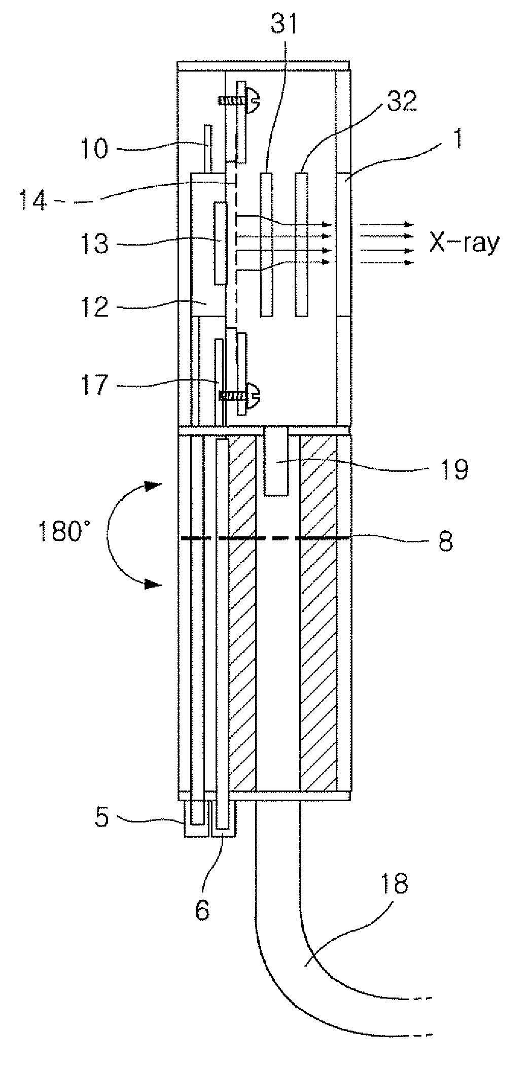
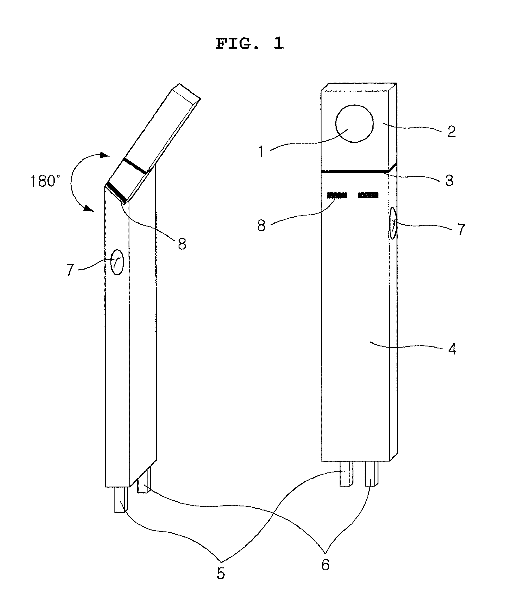
[0031]FIG. 1 is a diagram illustrating a rotatable carbon nanotube-based X-ray tube system in the form of a pen according to an embodiment of the present invention.

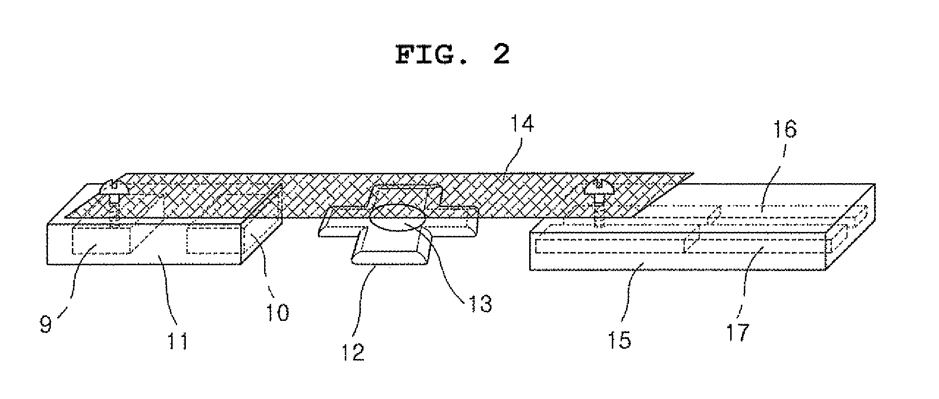
[0032]Referring to FIG. 1, the X-ray tube system according to an embodiment of the present invention includes an X-ray emission module 2 including an X-ray emission window 1, an X-ray emission module separator 3, an X-ray emission system body 4, a feed-through 5 for applying voltage to a carbon nanotube cathode portion 12 of FIG. 2 and a grid portion 14 of FIG. 2, a cable 6 for generating high voltage and a vacuum atmosphere in the system, a grid portion power supply switch 7 for ext...


PUM


Abstract

The present invention relates to applying an existing carbon nanotube X-ray tube for a dental X-ray imaging system that can replace a carbon nanotube electron emission source installed in a cathode portion. An X-ray tube system formed in a pen according to the present invention can be inserted in the oral cavity due to its thin thickness, thereby displaying an accurate image of an inner location of the oral cavity needing a diagnosis. For therapy of oral cancer requiring an appropriate amount of radiation therapy, since radiation can be directly irradiated to a diseased part, brachytherapy is enabled without concern of exposure dose of normal tissues. Therefore, when the system is commercialized, a great amount of distribution effect may be expected. The X-ray tube system that can be used for medical services such as a dental service includes an X-ray emission module emitting X-rays using a chipped nano-structured material, for example, carbon nanotube. The X-ray emission module is separable from a body in order to replace a cathode portion that is included in the X-ray emission module and is based on the nano-structured material.

Description

CROSS-REFERENCE TO RELATED APPLICATION[0001]This application claims priority from Korean Patent Application No. 10-2008-0055589, filed on Jun. 13, 2008, in the. Korean Intellectual Property Office, the entire disclosure of which is incorporated herein by reference.BACKGROUND OF THE INVENTION[0002]1. Field of the Invention[0003]The present invention relates to an X-ray tube system and a method thereof. More particularly, the present invention relates to a medical X-ray tube system for a dental diagnosis and an oral cancer therapy and the like based on nano material such as carbon nanotube that is proved to have the most excellent performance as an electron emission source, using a quantum-mechanical field emission principle of emitting electrons, and a method thereof.[0004]2. Description of Related Art[0005]Generally, a system for a dental diagnosis or an oral cancer therapy irradiates a light source toward the outside of the oral cavity of a patient and detects an image projected to...

Claims


Application Information

Patent Timeline
IPC IPC(8): A61B6/14H01J35/00H01J35/20
CPCA61B6/14A61B6/145H01J35/32H01J1/3048H01J35/065A61N5/1014A61C19/00A61C19/04B82Y20/00
Inventor KIM, JONG UKCHOI, HAE YOUNG
Owner KOREA ELECTROTECH RES INST
Why Eureka
Try Eureka