
Oil extraction device for pyrolysis of plastics waste material and extraction method thereof

a technology of oil extraction device and plastic waste material, which is applied in the direction of lighting and heating apparatus, combustion types, separation processes, etc., can solve the problems of low economic efficiency, poor oil extraction yield, and the majority of conventional pyrolysis systems, so as to improve economic efficiency and efficiently collect the pyrolysis gas

Inactive Publication Date: 2009-12-24
PULSE ENERGY
View PDF6 Cites 17 Cited by
  • Summary
  • Abstract
  • Description
  • Claims
  • Application Information

AI Technical Summary

Benefits of technology

[0010]The present invention has been made in view of the above problems, and an object of the present invention is to improve economical efficiency in an oil extraction system for pyrolyzing industrial waste materials such as waste plastic materials and waste Styrofoam, by pyrolyzing the waste materials in a pyrolysis chamber of a furnace, producing gas, efficiently collecting the pyrolyzed gas, condensing the gas, and separating oil and water.
[0011]Another object of the present invention is to reduce costs in waste treatment of waste plastic materials.
[0012]Another object of the present invention is to prevent environmental pollution of soil and air by avoiding landfill and incineration.
[0013]Further, another object of the present invention is to reduce import of energy sources in oil importing countries.
[0015]An oil extraction method according to another exemplary embodiment of the present invention utilizes the above oil extraction system to efficiently produce oil from industrial waste materials such as waste plastic materials and waste Styrofoam.
[0016]According to the above exemplary embodiments of the present invention, waste treatment costs of waste plastic materials may be reduced, environmental pollution of soil and air may be prevented by avoiding landfill and incineration, import of energy sources may be reduced in oil importing countries, and gas suction rate and oil extraction yield may be improved by sucking a large amount of produced gas by using gas suction pipes formed with bent ends in the primary pyrolysis chamber.

Problems solved by technology

However, most of conventional pyrolyzing systems have a disadvantage of low economical efficiency, because oil extraction yield is not satisfactory compared with installation and operation costs of the pyrolyzing systems.
Therefore, the conventional pyrolyzing systems are not successful in industrial applications.
However, films are formed in the holes by rotation of the outer hollow shaft while the inner furnace is rotated by a reduction motor, and the holes become blocked by the films.
Accordingly, gas is not smoothly exhausted and oil extraction yield is decreased.
However, this patent has a problem that gas containing oil is partially lost in the step of pre-melting the waste plastic materials.
That is, gas is partially lost in the step of pre-melting and compressing the waste plastic materials such as Styrofoam and vinyl, and in the step of pyrolyzing the waste plastic materials.
Additionally, the conventional waste treatment systems generally have a huge size.
However, the volume of gas produced by pyrolyzing waste materials is relatively small and efficiency of collecting the pyrolyzed gas for reprocessing is low, and thereby economical efficiency of the waste treatment facility becomes low.
Although hundreds of waste treatment systems were registered or applied for Korean patent, there is almost no waste treatment system practically running now.
This means that most of the waste treatment systems registered or applied for Korean patents are not economical yet.

Method used


Image

  • Oil extraction device for pyrolysis of plastics waste material and extraction method thereof
  • Oil extraction device for pyrolysis of plastics waste material and extraction method thereof
  • Oil extraction device for pyrolysis of plastics waste material and extraction method thereof

Examples


experimental example

[0130]Volume of a reactor that may be filled with waste materials; 6.944 D,[0131]Filling ratio; 80%[0132]Weight of filled material; 0.1003×0.8×0.45 (specific gravity)=2.5 t (input weight)[0133]Composition analysis of product; oil: 60%, gas: 20%, carbide (char): 15%, and moisture: 5%, wherein oil is separated by an oil-water separator because oil and moisture are mixed together.

[0134]Amount of products is calculated as follows.[0135]Oil: 2.5 ton×0.6÷0.87 (specific gravity)=1,724 L[0136]Gas: 2.5 ton×0.2=500 kg[0137]Carbide: 2.5 ton×0.15=375 kg[0138]Moisture: 2.5 ton×0.05=125 kg

[0139]Accordingly, oil of 1,724 L is produced from 2.5 ton of waste materials and production efficiency is high.

[0140]Energy balance for producing oil is described as follows.

[0141][0142]Type of waste material: Waste tire[0143]Filling amount: 2.5 ton / batch (Specific gravity is applied.)[0144]Composition of product

[0145]1) Oil: 45%˜50%→Applied value: 50%

[0146]2) Gas: 10%˜15%→Applied value: 15%

[0147]3) Carbide: 25...


PUM

PropertyMeasurementUnit
suction rateaaaaaaaaaa
shapeaaaaaaaaaa
volumeaaaaaaaaaa

Abstract

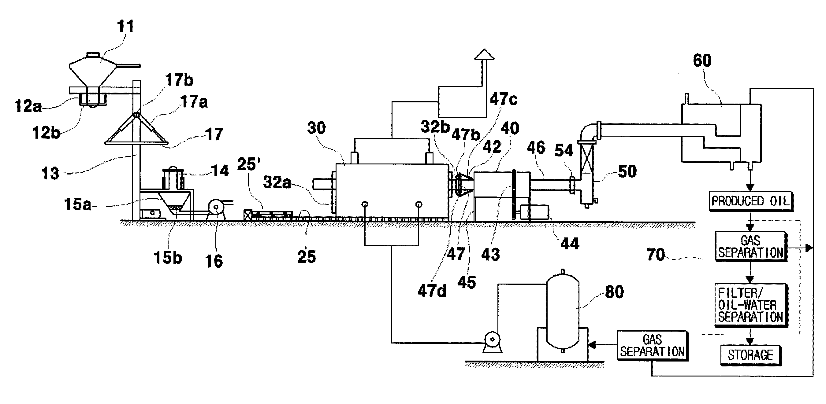
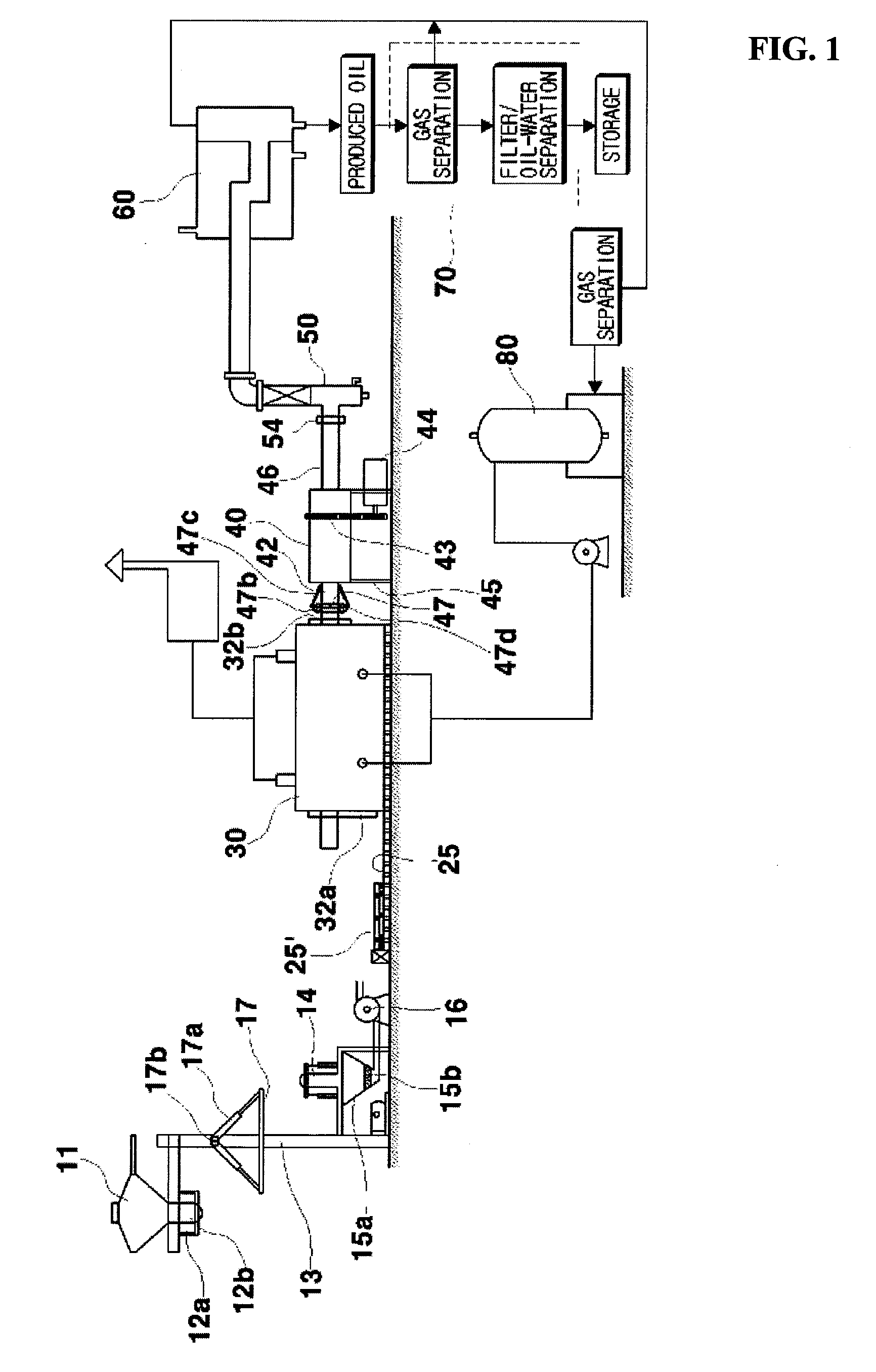
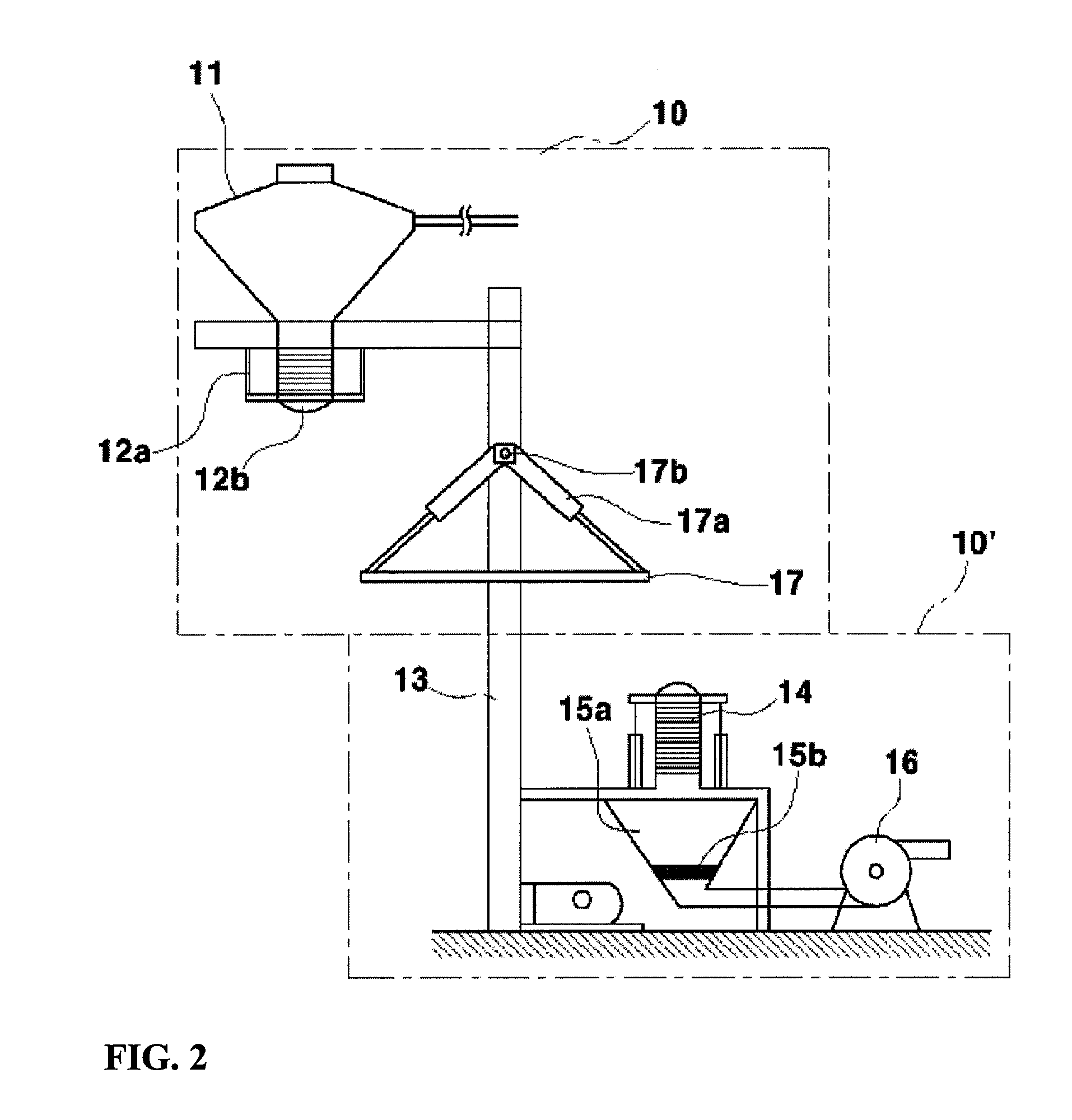
An oil extraction system and method for pyrolyzing waste plastic materials are disclosed. The oil extraction system includes: a waste feeding device for supplying waste plastic materials contained in a hopper to a primary pyrolysis chamber through a feed inlet, wherein the primary pyrolysis chamber pyrolyzes the supplied waste plastic materials; a double jacket furnace having a burner and for heating the primary pyrolysis chamber loaded into a burning room of the furnace; a rotation device for rotating the primary pyrolysis chamber loaded into the burning room of the furnace; a secondary pyrolysis chamber for re-pyrolyzing gas produced in the primary pyrolysis chamber, and for separating carbides and residue; a condenser for liquefying the gas separated from the secondary plyrolysis chamber by compression and forming oil; and an oil-water separator for separating oil and water condensed in the condenser.

Description

BACKGROUND OF THE INVENTION[0001]1. Field of Invention[0002]The present invention relates to an oil extraction system and method for pyrolyzing waste plastic materials, and more particularly, to an oil extraction system and method for producing oil from industrial wastes such as waste plastic materials and waste Styrofoam, by pyrolyzing the industrial wastes in a pyrolysis chamber of a furnace, condensing gas produced by pyrolysis, and separating oil and water. The oil extraction system according to the present invention improves efficiency of gas collection in a pyrolysis process, and thereby oil production efficiency and thereby increasing economical efficiency.[0003]2. Description of the Related Art[0004]Various oil extraction systems using pyrolysis of industrial wastes such as waste plastic materials, waste Styrofoam, and waste tires, have been introduced.[0005]However, most of conventional pyrolyzing systems have a disadvantage of low economical efficiency, because oil extract...

Claims


Application Information

Patent Timeline
Patent Type & Authority Applications(United States)
IPC IPC(8): C10B57/04C10B1/00
CPCC10B47/30C10B53/07F23G2900/50205C10G1/10C10B57/02Y02P20/143B01D46/00B01D53/002B29B17/02C10G1/04F23G5/027F23G7/06F23G2209/28B09B3/80B09B3/40
Inventor JOO, YONG SUP
Owner PULSE ENERGY
Learn More