Lateral ultra-high efficiency solar cell

Active Publication Date: 2009-12-31
NORTHROP GRUMMAN SYST CORP
View PDF18 Cites 21 Cited by
  • Summary
  • Abstract
  • Description
  • Claims
  • Application Information

AI Technical Summary

Benefits of technology

[0024]The disclosed invention is intended for surface mounted portable power and recharging applications where compactness combined with high efficiency is key due the low available surface area—such as on a cell phone, Blackberry, iPod, or a soldiers helmet / backpack. Or more simply, the solar cell technology that offers the highest efficiency in the thinnest and lightest form factor combined with the lowest manufacturing cost will win—which is exactly what the disclosed lateral multi-junction solar cell concept offers. An interesting and fairly topical application for this technology would be as a car rooftop mounted battery re-charger for a plug-in hybrid automobile. A 30% efficient solar array covering most of a cars roof would provide about 1.5 Kw, which is enough battery recharging power for between 5 to 10 miles of driving range—assuming the car is able to sit out in the sun most of the day. For typical short daily commutes of approximately 20 miles, this easily translates into >80 mpg of equivalent fuel efficiency.

Problems solved by technology

However, while the DC current is maximized with a small Eg (0.95 eV), the output voltage (V) is much less, limiting the maximum solar cell efficiency to approximately 30% (V×I).
Single energy band-gap (single junction) solar cells are considered to have a fairly low theoretical upper efficiency limit.
However, tandem cells require extremely complex processing for both lattice and current matching; typically can not be contacted separately; plus require complex and transparent vertical tunnel junctions to connect in a series manner the vertically stacked solar cells.
Lattice mismatch can lead to a number of problems that degrade energy efficiency, including high defect density, rough surface morphology—plus epitaxial layer cracking, bowing, and / or warping (i.e., vertically stacked tandem cells can end up resembling both the shape as well as the surface of a potato chip).
However, laying single-bandgap cells next to each other (instead of being vertically stacked) eliminates the efficiency gains—unless the incident sunlight can somehow be spectrally split and then concentrated.
However, as evident in FIG. 6 (prior art), the illustrated lateral solar cell architecture is not very compact—as compared to a vertical tandem multi-junction cell—with the ‘add-on’ optics increasing the overall solar cell thickness by at least 1 cm.
Additionally, the illustrated ‘bulky’ macro-optics configuration results in quite a bit of empty or unused space between the solar cells—increasing the overall solar panel area as compared to a comparable performance vertical tandem cell.
In addition to not being very compact (thin), known lateral solar cells (see FIG. 6 as an example) also involve a fairly complex and expensive assembly process that requires precise alignment of external optics to the individual solar cells.

Method used


Image

  • Lateral ultra-high efficiency solar cell
  • Lateral ultra-high efficiency solar cell
  • Lateral ultra-high efficiency solar cell

Examples


Embodiment Construction

[0038]So that the manner in which the above recited features, advantages and objects of the present invention are attained can be understood in detail, more particular description of the invention, briefly summarized above, may be had by reference to the embodiment thereof that is illustrated in the appended drawings. In all the drawings, identical numbers represent the same elements.

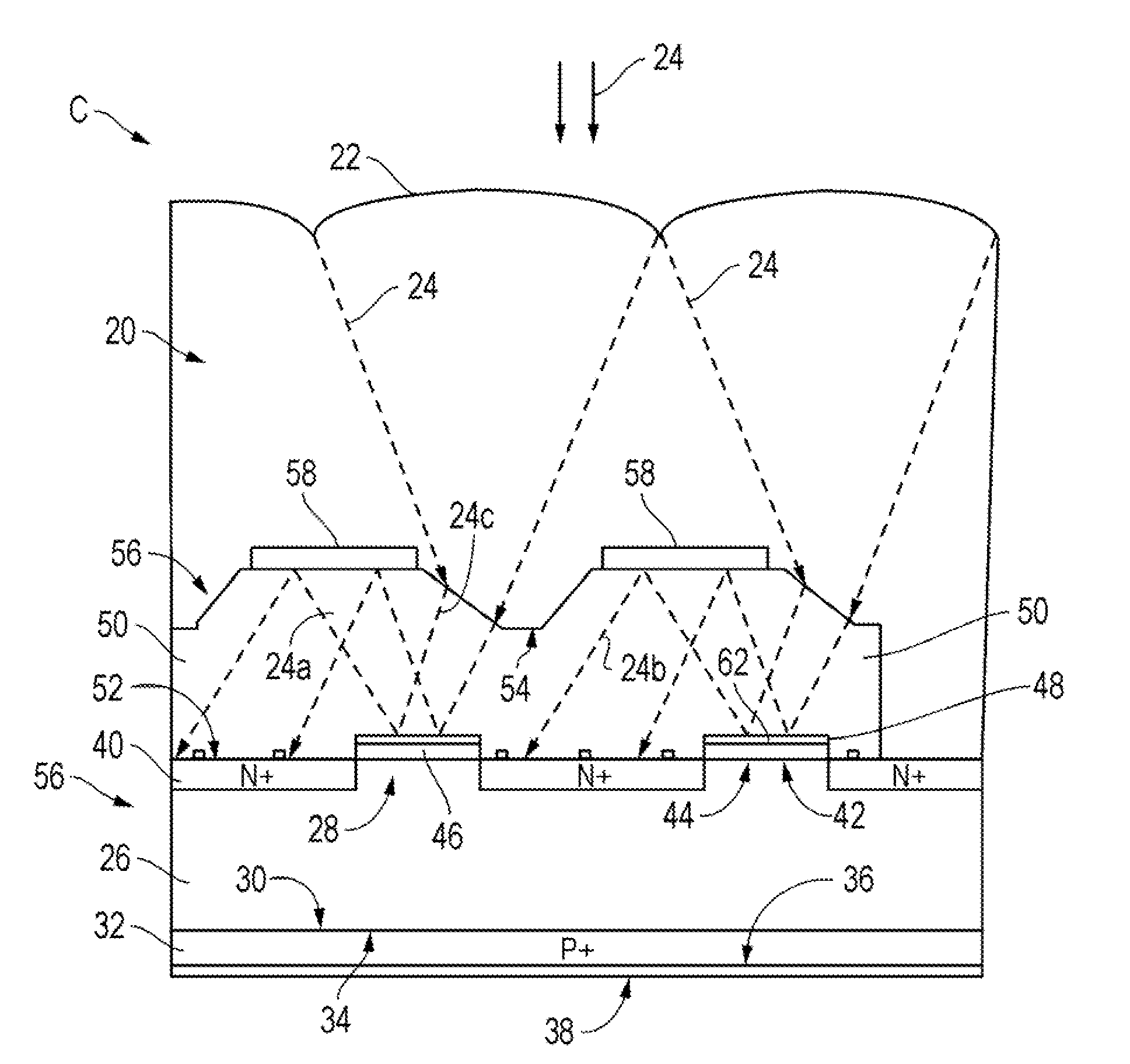
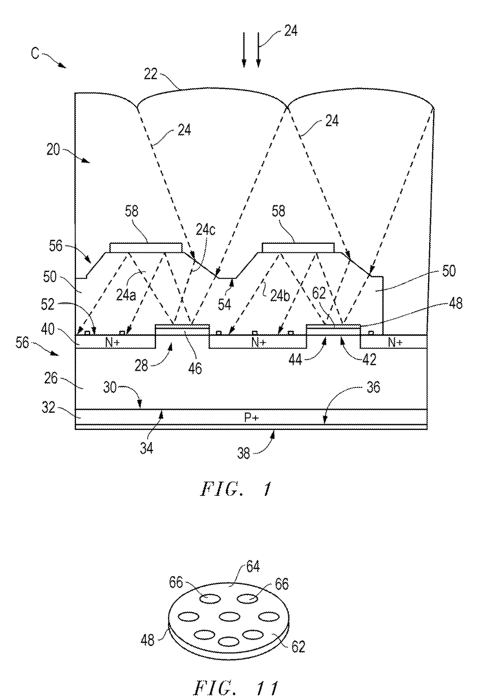
[0039]Referring particularly to FIG. 1, a high-efficiency lateral multi-junction tandem solar cell C of the present invention includes a micro-lens layer 20 that has an upper surface 22 formed into a micro-lens configuration to concentrate incident light or signal 24 impinging on the upper surface 22 of the solar cell C. The micro-lens layer 20 is preferably formed from a low refractive index material.

[0040]A primary, such as a P− type, semiconductor substrate slab layer 26, preferably of Silicon (Si), has an upper surface 28 and a lower surface 30. A comparable, such as a P+ type, semiconductor layer 3...


PUM


Abstract

A high-efficiency lateral multi-junction solar cell (C) includes ultra-low profile planar spectral band splitting micro-optics having a shortpass filter (48) reflecting desired frequencies of light (24) to a reflective mirror (58) combined with spectrally optimized photovoltaic (solar) cells.

Description

BACKGROUND OF THE INVENTION[0001]1. Technical Field[0002]The invention relates to the field of solar cells, and more particularly to a solar cell which includes an array of long and short wavelength photovoltaic cells on a substrate.[0003]2. Background Art[0004]Solar cells are solid-state devices that directly convert sunlight into electricity. This conversion is typically called the photovoltaic effect, which is the physical process through which the solar cell converts photons from incident sunlight directly into electricity—with the photon energy (Eph proportional to the incident sunlight's wavelength (λ) with Eph=1.24 / λ. Incident light on the solar cell produces both a DC current (I) and voltage (V) that delivers electric power (Power=V×I) to an external load.[0005]Under illumination, incident photons are absorbed, creating electron-hole pairs. The electron-hole pairs are separated and collected by an internal electric field—typically a PN junction—followed by the movement of hi...

Claims


Application Information

Patent Timeline
IPC IPC(8): H01L31/00H01L31/18
CPCF24J2/06F24J2/085G02B3/0056G02B27/1086G02B27/123H01L31/0547H01L31/03048Y02E10/52Y02E10/544H01L31/0549H01L31/0543G02B27/141F24S23/00F24S23/31Y02P70/50
Inventor SMITH, JOSEPH T.HALVIS, JAMES N.KNIGHT, THOMAS J.
Owner NORTHROP GRUMMAN SYST CORP
Why Eureka
Try Eureka