Energy storage system and method for storing and supplying energy

a technology of energy storage and energy supply, which is applied in the direction of lighting and heating apparatus, electric generator control, greenhouse gas reduction, etc., can solve the problem of very limited energy capacity of such systems, and achieve the effect of large energy storage quantities, high availability, and sufficient capacity and power outpu

Active Publication Date: 2009-12-31
SIEMENS ENERGY GLOBAL GMBH & CO KG
View PDF7 Cites 55 Cited by
  • Summary
  • Abstract
  • Description
  • Claims
  • Application Information

AI Technical Summary

Benefits of technology

[0034]Generally, the inventive method has advantages as the inventive energy storage system has.
[0035]The present invention provides a large scale energy storage system which can store very large quantities of energy. Compared to existing storage systems the amount is between factors of 10-100 larger. In conjunction with a renewable energy source, for example a big wind power plant, it could provide sufficient capacity and power output that the two systems will appear to the grid operator like a conventional power plant with its high availability and dispatchability.
[0036]Large energy storage systems will avoid to turn down or even to shut-off renewable energy generation in case of low demand as it happens when generation management needs to be applied. The introduction of a high pressure electrolyser improves significantly the system efficiency and power density in contrast to systems which would not use one. Furthermore, the heat recovery loops at the high pressure hydrogen compressor, at the high pressure hydrogen expander and at the fuel gas pre-heating increase the efficiency of the storage.

Problems solved by technology

Water and compressed air do not have a high specific power density and therefore the energy capacity of such systems is very limited.

Method used


Image

  • Energy storage system and method for storing and supplying energy
  • Energy storage system and method for storing and supplying energy
  • Energy storage system and method for storing and supplying energy

Examples


first embodiment

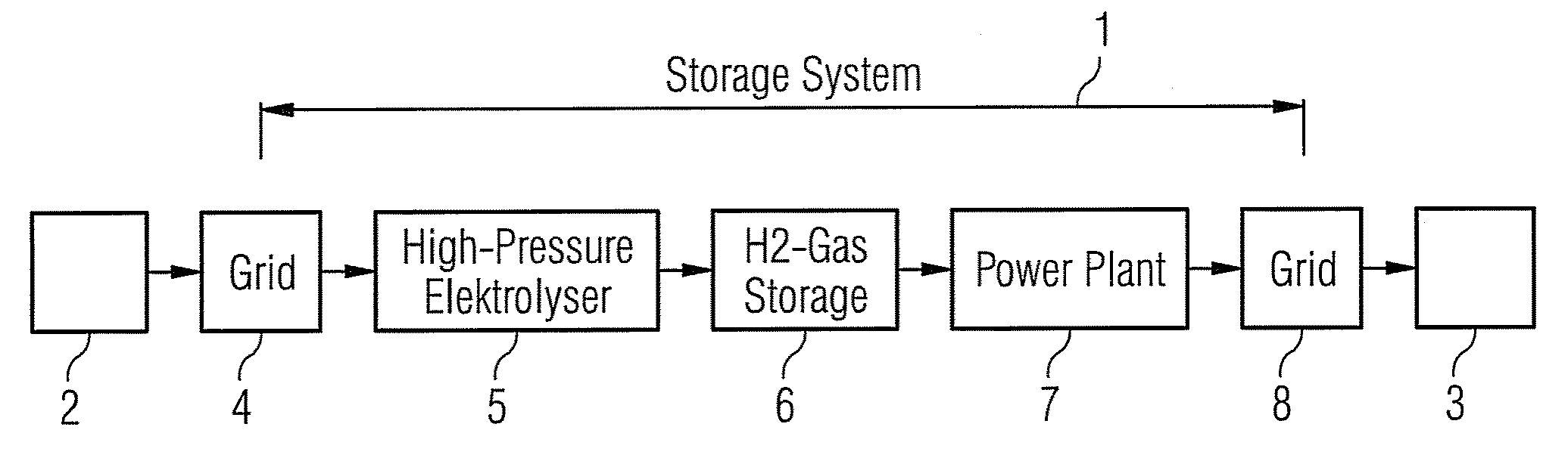
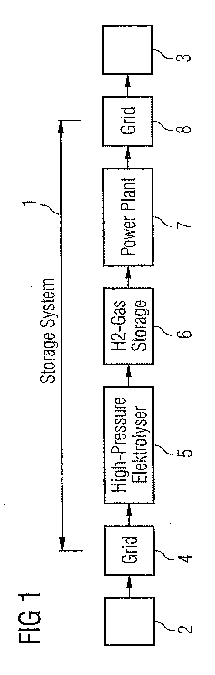
[0040]the present invention will now be described with reference to FIG. 1. FIG. 1 schematically shows an inventive energy storage system 1, which comprises a high-pressure electrolyser 5, a hydrogen gas storage 6, a power plant 7 and grid connections 4, 8. Electrical energy, for example renewable energy, coming from an electrical energy delivery unit 2 is delivered to the high pressure electrolyser 5 by means of a grid 4. In the high pressure electrolyser 5 hydrogen is separated from water by means of electrolysis. The hydrogen is then stored in the hydrogen gas storage 6. When needed, the stored hydrogen is supplied to the power plant 7. The electrical energy produced by the power plant 7 is then supplied to a grid 8.

second embodiment

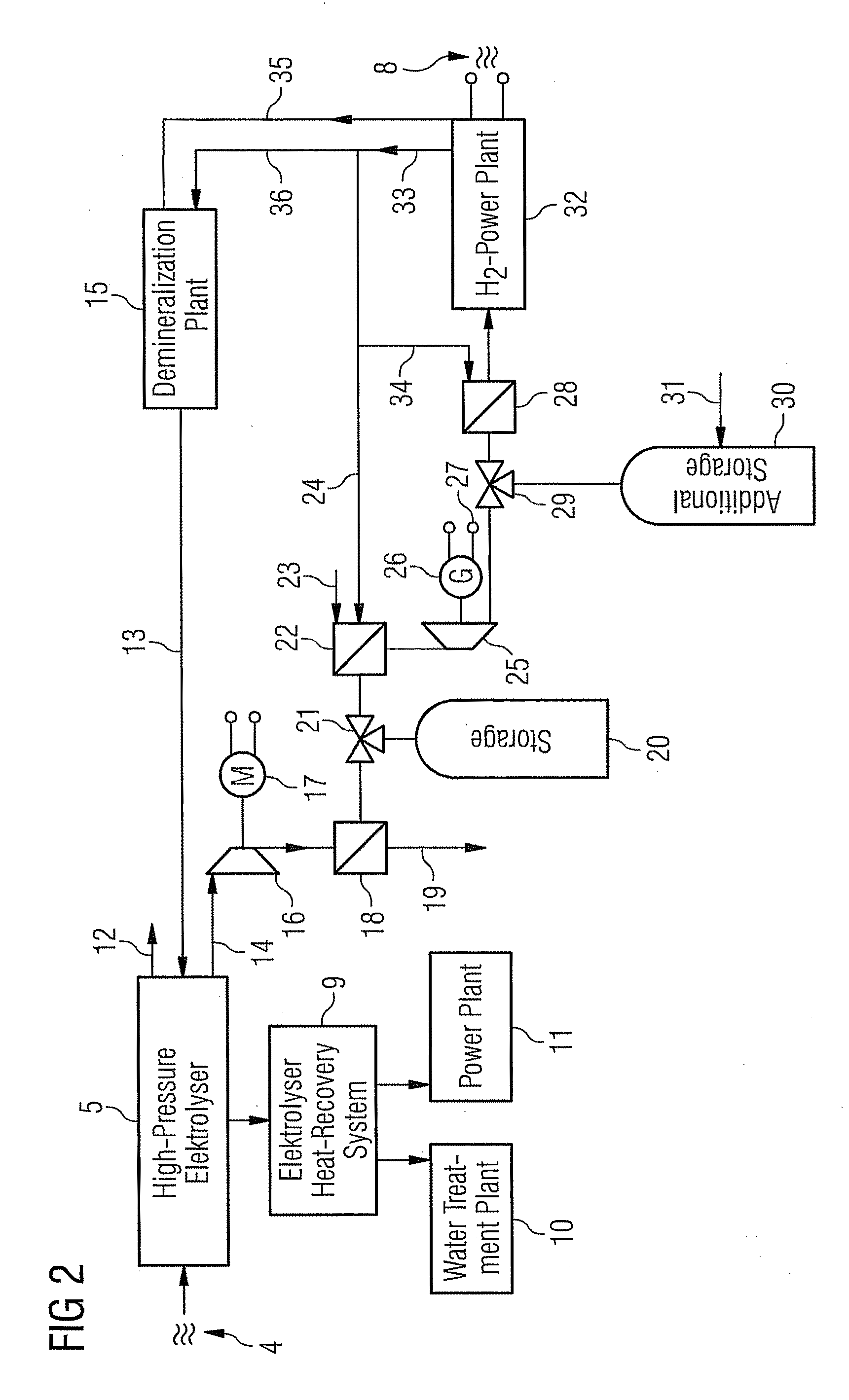
[0041]the present invention will now be described with reference to FIG. 2. FIG. 2 schematically shows an example for a detailed embodiment of the inventive energy storage system 1.

[0042]FIG. 2 shows a high pressure electrolyser 5 which is delivered with electrical energy by means of a grid 4. Water 13 coming from a demineralisation plant 15 is guided to the high-pressure electrolyser 5. In the high pressure electrolyser 5 the water 13 is decomposed into oxygen 12 and hydrogen 14. The high-pressure electrolyser 5 is further connected to an electrolyser heat-recovery system 9. The heat which is recovered by means of the electrolyser heat-recovery system 9 can be used for a water treatment plant 10 and / or for a power plant 11, for example. The water treatment plant 10 can especially be part of the demineralisation plant 15 which demineralises the water 13 for the high-pressure electrolyser 5.

[0043]The separated hydrogen from the high-pressure electrolyser 5 is guided to a hydrogen com...


PUM

PropertyMeasurementUnit
pressureaaaaaaaaaa
electrical energyaaaaaaaaaa
energyaaaaaaaaaa

Abstract

An energy storage system is provided which includes an electrolyser a hydrogen gas storage and a power plant. The electrolyser is connected to the hydrogen gas storage and the hydrogen gas storage is connected to the power plant. Furthermore, a method for storing and supplying energy is provided which includes delivering electrical energy to an electrolyser; decomposing water into oxygen and hydrogen gas by means of the electrolyser; storing the hydrogen gas; supplying the stored hydrogen gas to a power plant; and producing electrical energy via of the power plant.

Description

CROSS REFERENCE TO RELATED APPLICATIONS[0001]This application claims priority of European Patent Office application No. 08011545.4 EP filed Jun. 25, 2008, which is incorporated by reference herein in its entirety.FIELD OF INVENTION[0002]The present invention relates to an energy storage system and to a method for storing and supplying energy.BACKGROUND OF INVENTION[0003]Renewable energy is the choice of today to reduce CO2 emissions and to reduce the reliance on other primary energy sources. Renewable energy can replace a significant amount of the existing conventional power plants. The drawback of this source is that it is not always available with the needed power output and that it has a limited controllability.SUMMARY OF INVENTION[0004]The feed in of renewable energy depends also on the availability of the source itself and of the remaining capacity of the grid. To reach the ultimate goal of the society to reduce the CO2 emissions and to become independent of fossil fuels the co...

Claims


Application Information

Patent Timeline
Patent Type & Authority Applications(United States)
IPC IPC(8): H02K7/18C25B9/00F02C6/14
CPCC25B1/12F01K23/00F01K25/005Y02E60/366Y02E20/16Y02E60/324F22B1/003Y02P20/129C25B1/04C25B9/05Y02E60/36Y02E70/30Y02E60/32
Inventor WOLF, ERIK
Owner SIEMENS ENERGY GLOBAL GMBH & CO KG
Why Eureka
Try Eureka