Probe and system for electron spin resonance imaging

a technology of electron spin resonance and probe, which is applied in the field of esr imaging, can solve the problems of limiting the size of the specimen, requiring a large device, and needing to insert the specimen into the imaging device, so as to improve the permittivity and quality factor, and improve the sensitivity of the resonator

Inactive Publication Date: 2010-01-07
TECHNION RES & DEV FOUND LTD
View PDF6 Cites 14 Cited by
  • Summary
  • Abstract
  • Description
  • Claims
  • Application Information

AI Technical Summary

Benefits of technology

[0018]Cooling the resonator according to embodiments of the present invention increases the resonator's permittivity and quality factor, and this improves the sensitivity of the resonator and allows working with smaller resonators than those useful with lower permittivity materials or at higher temperatures.
[0019]Smaller resonators allow closer positioning of gradient coils. When the distance between the coils and the specimen is short, the coils provide at the specimen larger gradients, and allow better spatial resolution. Thus, providing cooled dielectric resonators according to some embodiments of the present invention allows exceptional sensitivity and resolution.

Problems solved by technology

One drawback of the in-situ geometry is the need to insert the specimen into the imaging device.
This limits the size of the specimen, or requires a large device.
A drawback of induction detection is its notoriously low Signal-to-Noise-Ratio (SNR), which requires, under ambient conditions, to sense at least 107 spins per voxel.
These SNR limitations are also reflected by the limited image resolutions currently achievable with induction detection-based electron spin resonance imaging.
This wide variety of techniques, however, has very limited spectroscopic and 3D imaging capability, and often requires very complicated sample preparation procedures, which makes its practical use very difficult.
WO2005 / 073695 describes an on-chip magnetic resonance spectroscopy in ex-situ geometry, but does not provide imaging possibilities, and does not operate in the induction detection method.

Method used


Image

  • Probe and system for electron spin resonance imaging
  • Probe and system for electron spin resonance imaging
  • Probe and system for electron spin resonance imaging

Examples


Embodiment Construction

[0040]In the following description subtitles are provided to ease the reading of the detailed description, however, these subtitles are not intended to limit the interpretation of the terms used herein, or to provide basis for interpreting any term.

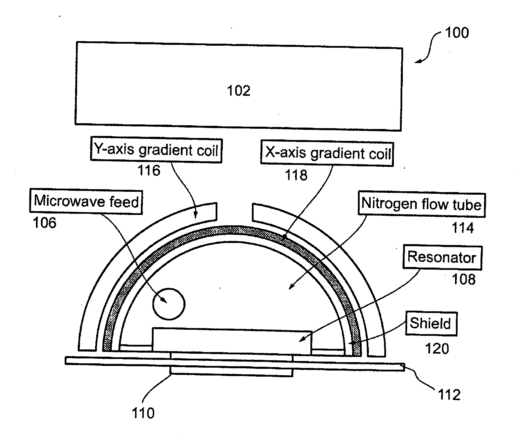
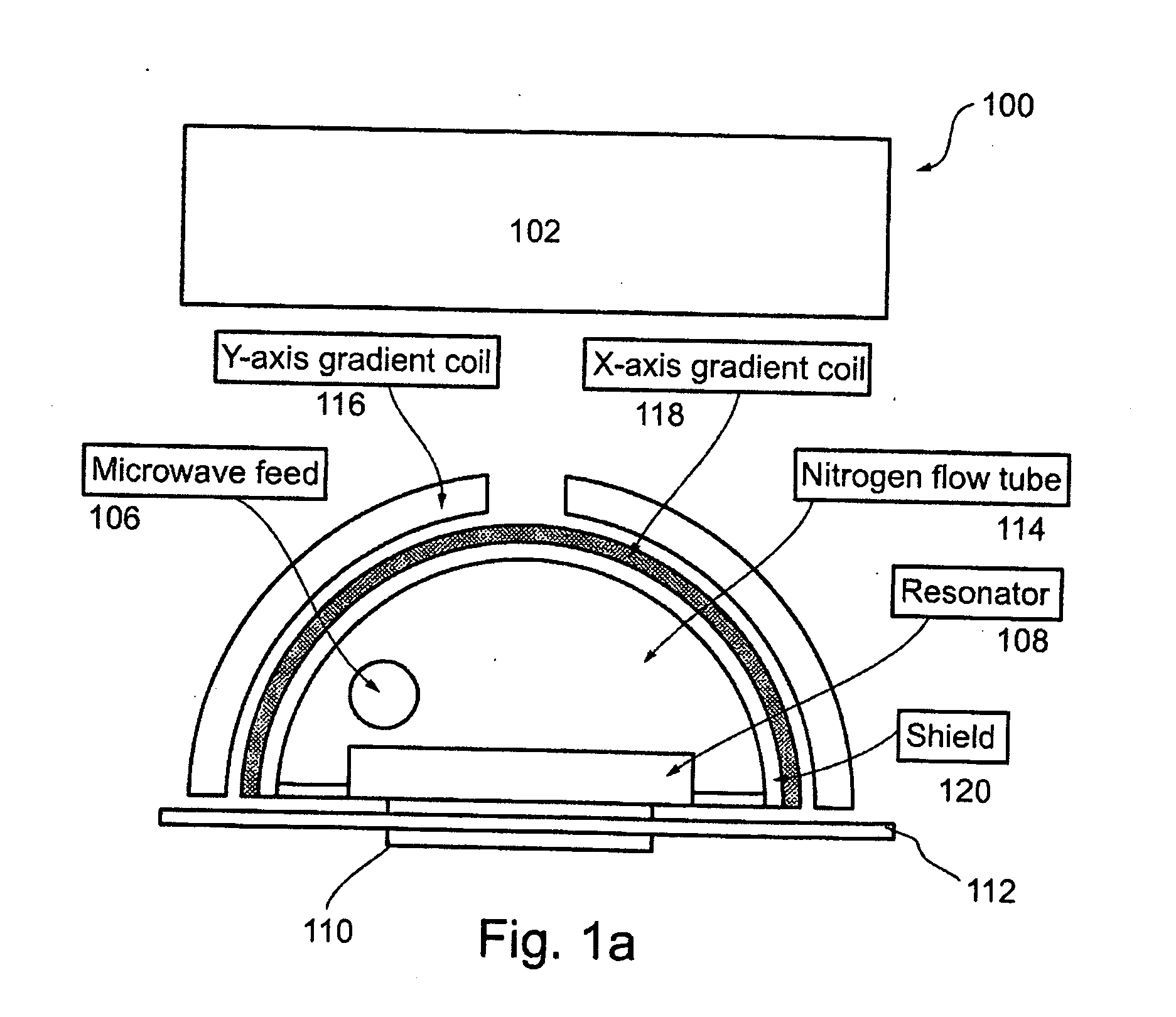
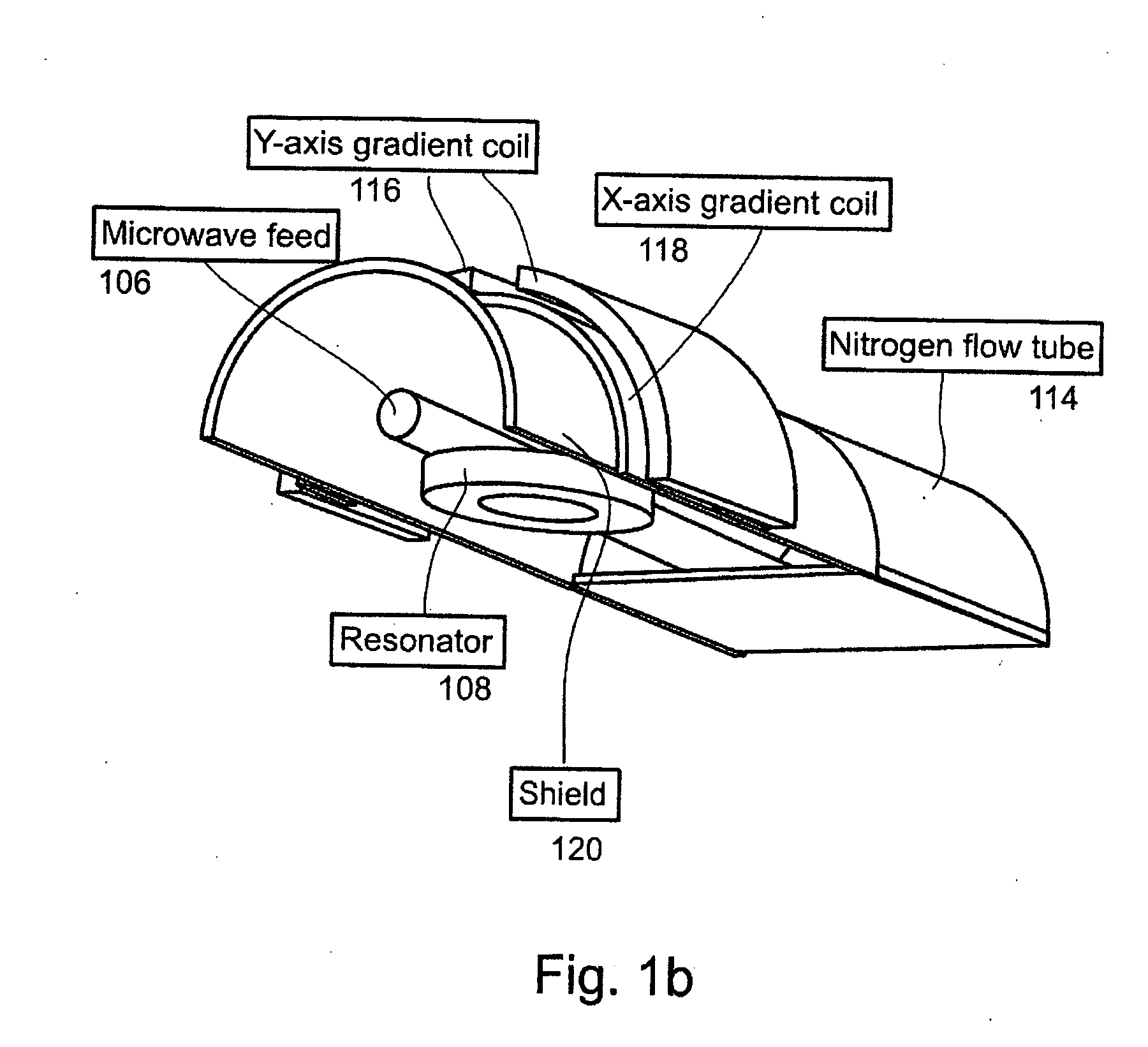
[0041]FIG. 1A is a schematic illustration of a cross-section in an ESR imaging probe 100 according to an exemplary embodiment of the invention. FIG. 1B is an isometric view of a similar probe, not comprising the permanent magnet. In this embodiment, the static magnetic field is provided by a source that does not form part of the probe.

[0042]Probe 100 comprises a permanent magnet 102, a microwave feed 106, a resonator 108, and a connection (see line going from k to g and from there g to c in FIG. 4) to a processing unit (c in FIG. 4).

[0043]In an exemplary embodiment of the invention, probe 100 is provided as an integral unit, with magnet 102 attached to the other probe parts as to move with them. In this embodiment, a scan of specimen may ...


PUM


Abstract

ESR imaging probe, system, and method are described. The probe is an ex-situ probe, the system comprises the probe and configured for operating the probe, and the method comprises detecting ESR from outside a resonator of the probe. An exemplary embodiment of a probe according to the invention comprises a cooled dielectric resonator, and one sided gradient coils. An exemplary embodiment of the system comprises source current that is configured to supply to the gradient coils currents of up to 100 A in pulses shorter than 1 μsec.

Description

FIELD OF THE INVENTION[0001]The present invention relates to ESR imaging and in particular to a probe and a system for ESR imaging and a method of producing an ESR image.BACKGROUND OF THE INVENTION[0002]Electron spin resonance imaging (ESR imaging) is a technique for obtaining spatially resolved ESR-based data from samples. ESR-based data is data obtained by applying on the sample a static magnetic field, exciting electron spins in the sample by electromagnetic waves, and detecting irradiation created by the electron spins as a result of their excitation.[0003]The spatially resolved ESR-based data can, for example, provide information about chemical structure, eluci date biological functions, enable non-invasive medical diagnosis, and be used to solve material science problems.[0004]In classical ESR detection method, termed “induction detection”, the imaged specimen is put inside a microwave resonator, and is subjected to a static magnetic field and to microwave radiation. Within th...

Claims


Application Information

Patent Timeline
Patent Type & Authority Applications(United States)
IPC IPC(8): G01R33/48G01R33/44
CPCG01N24/10G01R33/60G01R33/385G01R33/3808
Inventor BLANK, AHARONSHTIRBERG, LAZAR
Owner TECHNION RES & DEV FOUND LTD
Why Eureka
Try Eureka