Reflective optical element for EUV lithography device

a technology of euv lithography and reflectivity, which is applied in the direction of instruments, lighting and heating apparatus, originals for photomechanical treatment, etc., can solve the problems of phase angle shift and reduce the reflectivity at the operating wavelength, and achieve the effect of the highest possible reflectivity

Active Publication Date: 2010-02-04
CARL ZEISS SMT GMBH
View PDF9 Cites 52 Cited by
  • Summary
  • Abstract
  • Description
  • Claims
  • Application Information

AI Technical Summary

Benefits of technology

[0008]It is an object of the present invention to provide a reflective optical ele

Problems solved by technology

The basic structure of this multilayer system with the first and second additional layer is based on the finding that many materials which are capable of increasing the reflectivity react chemically with the basic materials of the multilayer system, in particular the spacer material, so that additional layers of undesired material form, which on one hand have a n

Method used


Image

  • Reflective optical element for EUV lithography device
  • Reflective optical element for EUV lithography device
  • Reflective optical element for EUV lithography device

Examples


Embodiment Construction

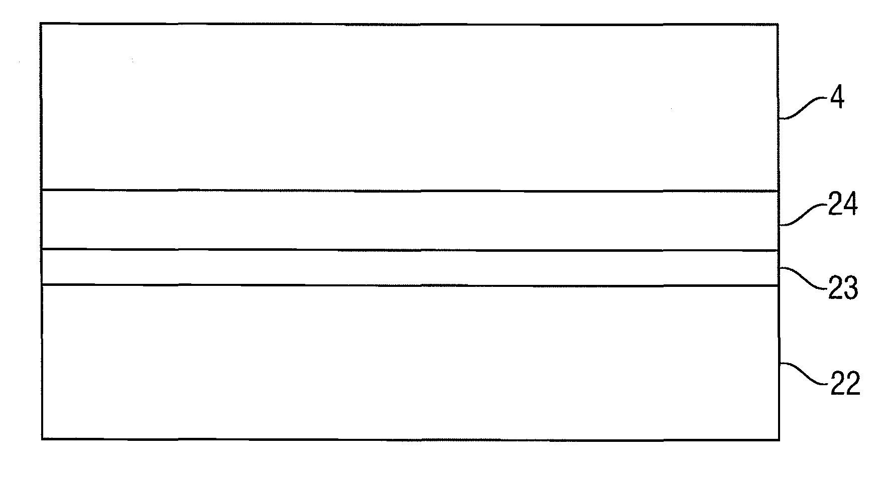
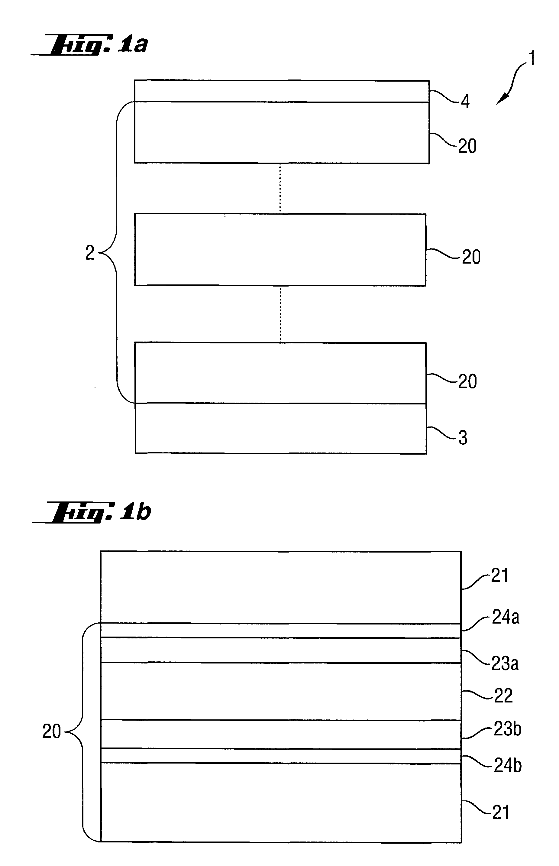
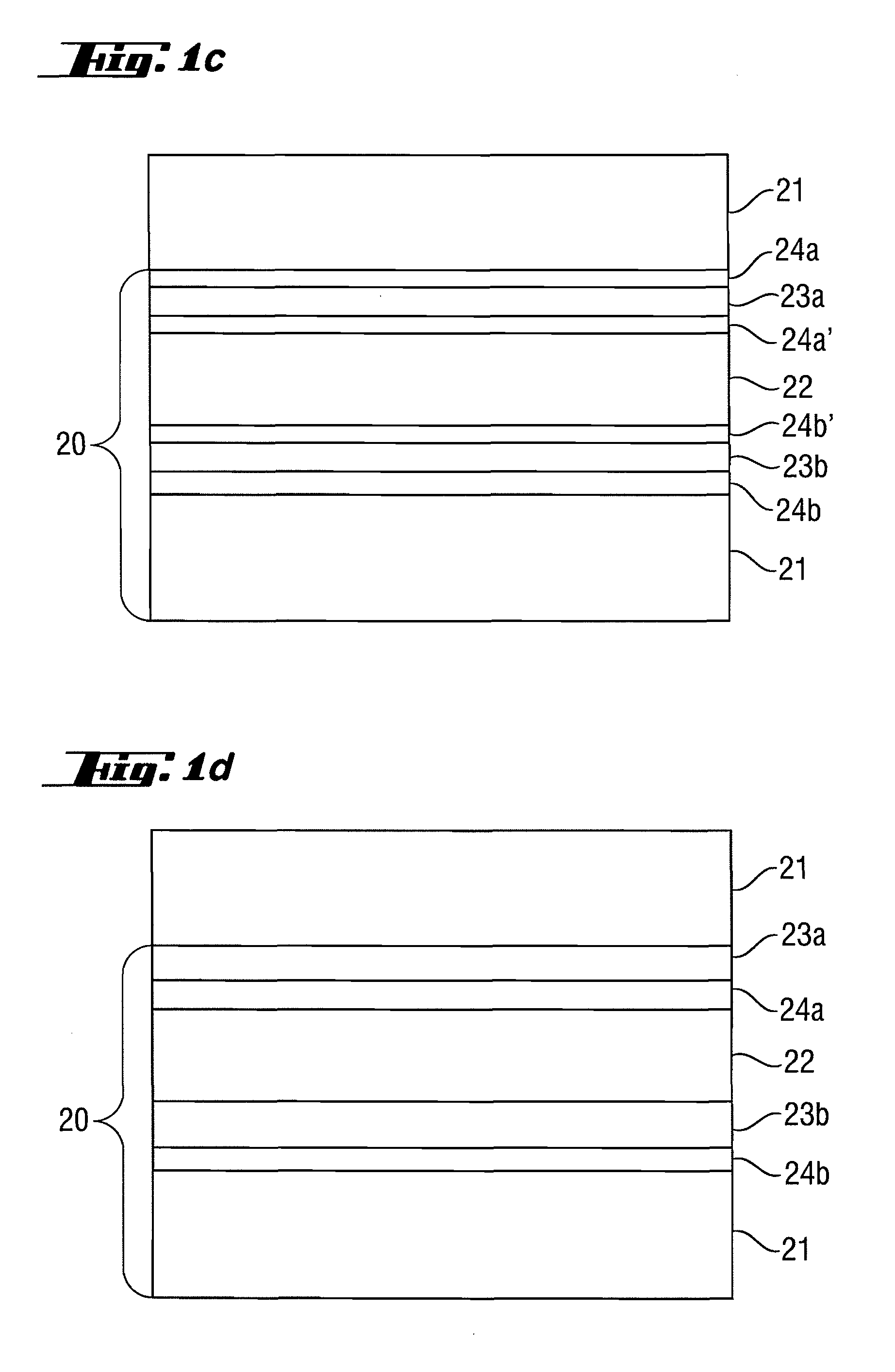
[0027]FIGS. 1a,b show an example of a reflective optical element 1 for the extreme ultraviolet and soft x-ray wavelength range, in particular for use in EUV lithography devices, e.g., as a photomask or as a mirror. FIG. 1a schematically shows the higher-order structure of the multilayer system 2. The multilayer system 2 has been produced in the present example by successively coating a substrate 3 using different materials having different complex indices of refraction. Moreover, a protective layer 4 was additionally applied to the multilayer system 2 for protection from external influences such as contamination. The protective layer 4 itself may be composed of multiple different material layers, which are inert to various contamination influences, suppress a chemical interaction with the multilayer system 2, and ensure an optical adaptation to the multilayer system 2, for example, to influence the optical properties such as the reflectivity of the reflective optical system 1 as lit...


PUM


Abstract

A reflective optical element exhibits an increase in the maximum reflectivity at operating wavelengths in the extreme ultraviolet or soft x-ray wavelength range. A first additional intermediate layer (23a, 23b) and a second additional intermediate layer (24a, 24b) are provided between the absorber layer (22) and the spacer layer (21), wherein the first additional intermediate layer increases the reflectivity and the second additional intermediate layer (24a,b) prevents chemical interaction between the first additional intermediate layer (23a,b) and the adjoining spacer layer (21) and/or the absorber layer (22).

Description

[0001]This is a Continuation of International Application PCT / EP2008 / 000842, with an international filing date of Feb. 2, 2008, which was published under PCT Article 21(2) in English, and the complete disclosure of which is incorporated into this application by reference.FIELD OF THE INVENTION [0002]The present invention relates to a reflective optical element for an operating wavelength in the extreme ultraviolet and soft x-ray wavelength range, in particular for use in EUV lithography devices, which has a multilayer system made of at least two alternating materials having different real parts of the index of refraction at the operating wavelength.[0003]Furthermore, the present invention relates to a projection system and an illumination system, in particular for an EUV lithography device, having at least one reflective optical element and to an EUV lithography device having at least one reflective optical element.BACKGROUND OF THE INVENTION [0004]Reflective optical elements for th...

Claims


Application Information

Patent Timeline
IPC IPC(8): G21K1/06
CPCG21K1/062B82Y10/00G21K1/06
Inventor YAKSHIN, ANDREY E.VAN DE KRUIJS, ROBBERT W. E.BIJKERK, FREDLOUIS, ERICNEDELCU, ILEANA
Owner CARL ZEISS SMT GMBH
Why Eureka
Try Eureka