Metal oxide coatings for electrically conductive carbon nanotube films

a technology of carbon nanotubes and metal oxide coatings, which is applied in the direction of natural mineral layered products, synthetic resin layered products, transportation and packaging, etc., can solve the problems of brittle ito films, difficult and expensive scaling up of both processes to cover large areas, and high cost, so as to prevent the degradation of composite materials

Inactive Publication Date: 2010-02-04
EIKOS
View PDF0 Cites 22 Cited by
  • Summary
  • Abstract
  • Description
  • Claims
  • Application Information

AI Technical Summary

Benefits of technology

[0012]It was surprisingly discovered that specific inorganic metal oxides, and combinations thereof, can be formed over a preexisting network of carbon nanotubes, preferably single-walled carbon nanotubes, producing novel materials with unique properties including improved stability of electrical, chemical and physical characteristics upon exposure to a plethora of environmental conditions.
[0026]Another embodiment is directed to a method further comprising depositing a polymeric coating on the composite. Preferably, the polymeric coating comprises polyester, polyurethane, polyolefin, fluoroplastic, fluoroelastomer, thermoplastic elastomer, polyvinylidene fluoride, polyvinyl fluoride, polychlorotrifluoroethylene, polyvinylalkyl vinyl ether, a melamine / acrylic copolymer, UV curable epoxy, a copolymer or polymer mixture, or combinations thereof. Preferably, the polymeric coating is adhesive. Preferably, the polymeric coating prevents degradation of the composite due to mechanical or physical stress. Preferably, the polymeric coating has an index of refraction which matches adjacent layers.

Problems solved by technology
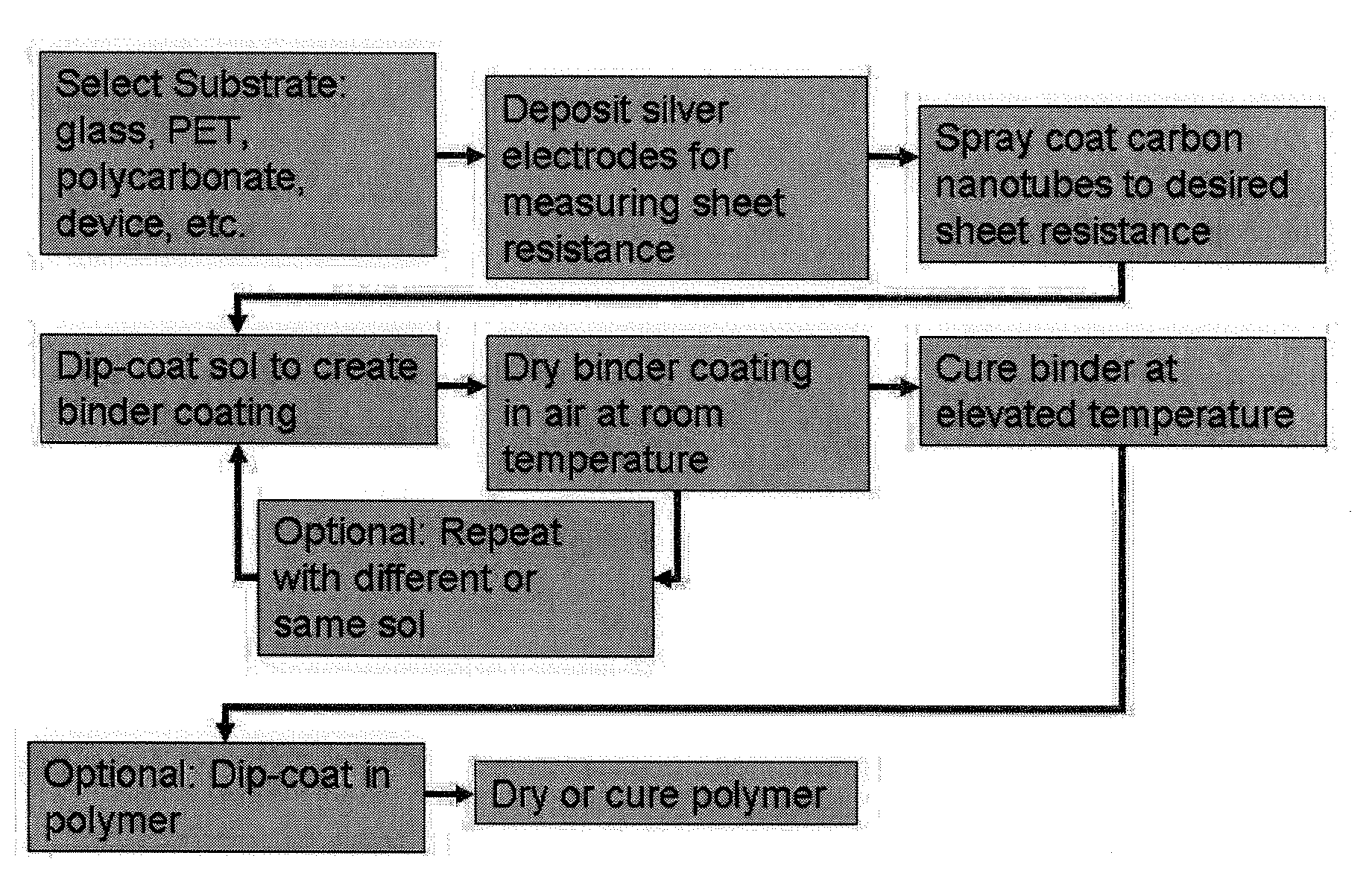
Both of the processes are difficult and expensive to scale up to cover large areas.
ITO also has some rather significant limitations: 1) ITO films are brittle (mechanical reliability concern for flexible applications such as in plastic displays, plastic solar voltaic, and wearable electrical circuitry); and 2) ITO circuits are typically formed by vacuum sputtering followed by photolithographic etching (fabrication cost may be too high for high volume / large area applications).
However, this ITO-filled system cannot match the electrical conductivity of a continuous ITO film.
Although they are still at a development stage, and have yet to reach the conduction level of an ITO film, the presence of dopants has an adverse effect on making these materials sensitive to environmentally induced changes in resistance and transparency.
Future electronic devices are limited in function and form by the current materials and processes utilized to create electrically conductive transparent layers.

Method used


Image

  • Metal oxide coatings for electrically conductive carbon nanotube films
  • Metal oxide coatings for electrically conductive carbon nanotube films
  • Metal oxide coatings for electrically conductive carbon nanotube films

Examples


example 1

ZnO Binder

[0084]To make a 3.7% weight zinc alkoxide sol, 46.82 grams of 2-Propanol were added into a 250 ml container. Next, 1.7947 grams of Zinc Methoxyethoxide (Gelest) was weighed into the same container. Concentrated Hydrochloric Acid was slowly added to the container until 1.3853 grams were added. A sonication bath is preferably used to dissolve the Zinc Methoxyethoxide. Care should be taken to not overshoot the amount of acid added as this may affect the properties the final coating. The solution should be stored in a tight sealing container to prevent moisture from entering the container and prevent evaporation of the 2-propanol. For larger batches, the ratio of reagents is listed in Table 1: Weights of reagents for producing Zn alkoxide sol of different quantity.

TABLE 1Weights of reagents for producing Zn alkoxide sol of different quantityCompoundFactor50 Grams100 Grams1000 GramsIPA0.936446.820093.64936.40Zinc0.0358951.79473.589535.8948MethoxyethoxideHCl0.0277051.38532.77052...

example 2

TiO2—ZnO Binder

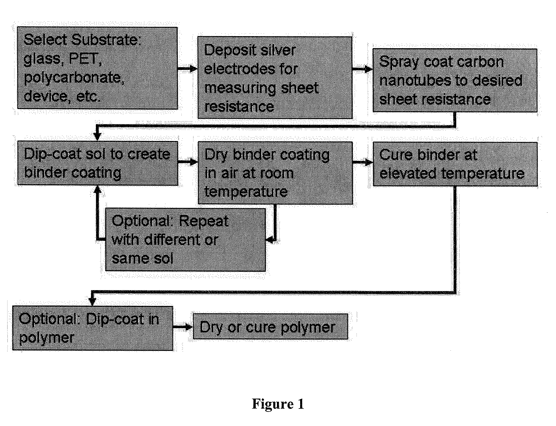
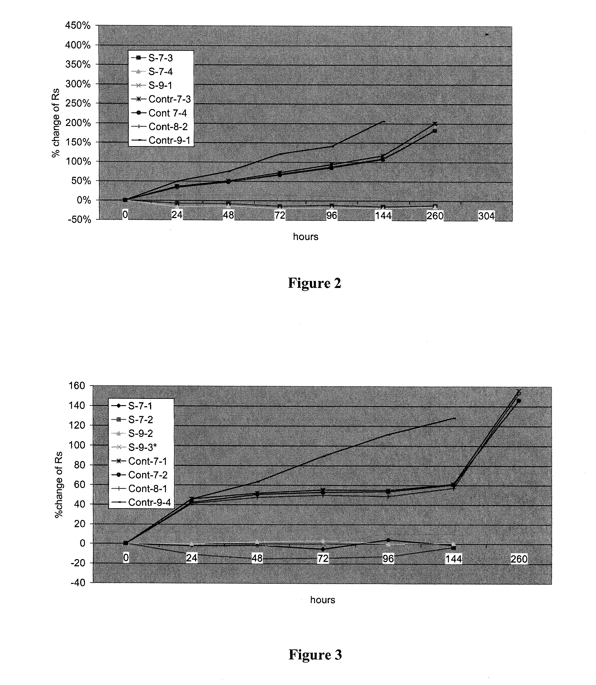
[0089]Glass slides coated with CNT were dip coated in 10.2% Ti butoxide sol (2 dips, at a speed of 3.33 inch / min), dried in air, and then dipped (4 dips, speed 4.07 inch / min) in 2.2% zinc alkoxide sol. The samples were then placed in the oven at 120 degrees C. for 2.5 hours. Controls of CNT on glass with no binder were placed in the oven under the same conditions. Samples were heat tested and measured as described above. Samples were placed in an oven at 80 degrees C. for heat testing. Sheet resistance of samples was measured after spraying, after curing the binder, at 24, 48, 72, 96, 144, and 260 hours. The data are listed in Table 4: Resistance of samples with Ti—Zn oxide binder during heating at 80 deg C. for up to 260 hours, compared to controls (Cont) of uncoated CNT layers:

TABLE 4Resistance of samples with Ti—Zn oxide binder during heating at 80 degC. for up to 260 hours, compared to controls (Cont) of uncoated CNT layersSprayedBinderSampleCNT / RR startR / 24R / 48R / ...

example 3

Al2O3—ZnO Binder

[0091]A solution of aluminum alkoxide was used for forming of Al2O3 binder. 10 g of aluminum butoxide were weighed out and put in a container. 90 g of absolute IPA were weighed out in the same container. Solution was mixed for 15 minutes for dissolving of alkoxide. The prepared transparent solution was stabilized by adding concentrated Hydrochloric Acid. The acid was added slowly drop-wise. A sonication bath is optionally used to help dissolve any solid deposit. See Table 6: Weights of reagents for producing Al alkoxide sol of different quantity for ratios of different batch sizes:

TABLE 6Weights of reagents for producing Al alkoxide sol of different quantityCompoundFactor50 Grams100 Grams1000 GramsIPA0.904590900Aluminum0.10510100ButoxideHCl0.010.5110

[0092]Glass slides coated with CNT were dip coated in 10% Al butoxide sol (3 dips, speed 3.3 inch / min), dried in air, and then dipped in 2.2% zinc alkoxide sol (4 dips, speed 2.57 inch / min). The samples were then placed i...


PUM

PropertyMeasurementUnit
temperaturesaaaaaaaaaa
thicknessaaaaaaaaaa
thicknessaaaaaaaaaa

Abstract

This invention are directed to methods and compositions preferably comprising non-silicate metal oxides as a treatment for transparent electrically conductive carbon nanotube coatings that prevents resistance changes during exposure to environmental conditions; both chemical effects (for example, water, heat, light, or other compounds) and physical effects (for example, abrasion, scratch, adhesion). The protective properties instilled by these coatings occur preferably through the careful selection of the appropriate metal oxide depending on the application.

Description

REFERENCE TO RELATED APPLICATIONS[0001]This application claims priority to U.S. Provisional Application No. 60 / 834,281, filed Jul. 31, 2006, and U.S. Provisional Application No. 60 / 826,783, filed Sep. 25, 2006, both entitled “Metal Oxide Coatings for Nanotube Conductive Films,” and both of which are specifically and entirely incorporated by reference.RIGHTS IN THE INVENTION[0002]This invention was made, in part, with support from the United States Department of Energy, under funding from Grant No. DE-FG36-05GO85035. Accordingly, the Unites States government has certain rights in this invention.BACKGROUND[0003]1. Field of Invention[0004]This invention is directed to compositions and methods of creating and maintaining the electrical conductivity of carbon nanotubes transparent electrically conductive layers and films by application of metal oxide materials in to the carbon nanotube network. The resulting transparent conductive layers are useful for forming electrodes and patterned ci...

Claims


Application Information

Patent Timeline
Patent Type & Authority Applications(United States)
IPC IPC(8): B32B7/02B32B9/00B32B27/32B32B17/06B32B27/36B32B27/38B32B27/40B32B27/30B32B27/28B05D5/12
CPCH01B1/04H01B1/18Y10T428/2495Y10T428/31507Y10T428/31511Y10T428/3154Y10T428/31551Y10T428/31786Y10T428/31938
Inventor TUREVSKAYA, EVGENIYA P.LANDIS, DAVID H.BRITZ, DAVID ALEXANDERGLATKOWSKI, PAUL J.
Owner EIKOS
Why Eureka
Try Eureka