

Method of manufacturing oriented body, molded body and sintered body as well as method of manufacturing permenant magnet
a technology of permenant magnets and molded bodies, which is applied in the direction of magnetic bodies, electric/magnetic/electromagnetic heating, magnetic materials, etc., can solve the problems of inability to obtain high orientation and improve magnetic properties, and achieve high orientation
- Summary
- Abstract
- Description
- Claims
- Application Information
AI Technical Summary
Benefits of technology
Problems solved by technology
Method used
Image

Examples
example 1
[0055]In Example 1, Nd—Fe—B alloy raw meal powder was manufactured as described below, an orienting step and a molding step were executed by using a below-described molding apparatus to thereby manufacture a predetermined molded body and, thereafter, a sintering step was executed in which the molded body was sintered in argon atmosphere at a temperature of 1050° C. for 4 hours, thereby obtaining a Nd—Fe—B sintered magnet.
[0056](Alloy Raw Meal Powder) As Nd—Fe—B sintered magnet, material having a composition of 25Nd-3Pr-1Dy-0.95B-1Co-0.2Al-0.05Cu-0.01Ga-0.05 Mo-bal.Fe was used to manufacture an alloy raw material by vacuum fusion and molding. The alloy raw material was once subjected to coarse grinding by e.g., hydrogen crushing step and then was subjected to fine grinding by e.g., jet mill fine grinding step to thereby obtain an alloy raw meal powder. As the molding conditions, i) after having vacuum-melted the above alloy it was molded into a water-cooled cupper book mold (box type...
example 2
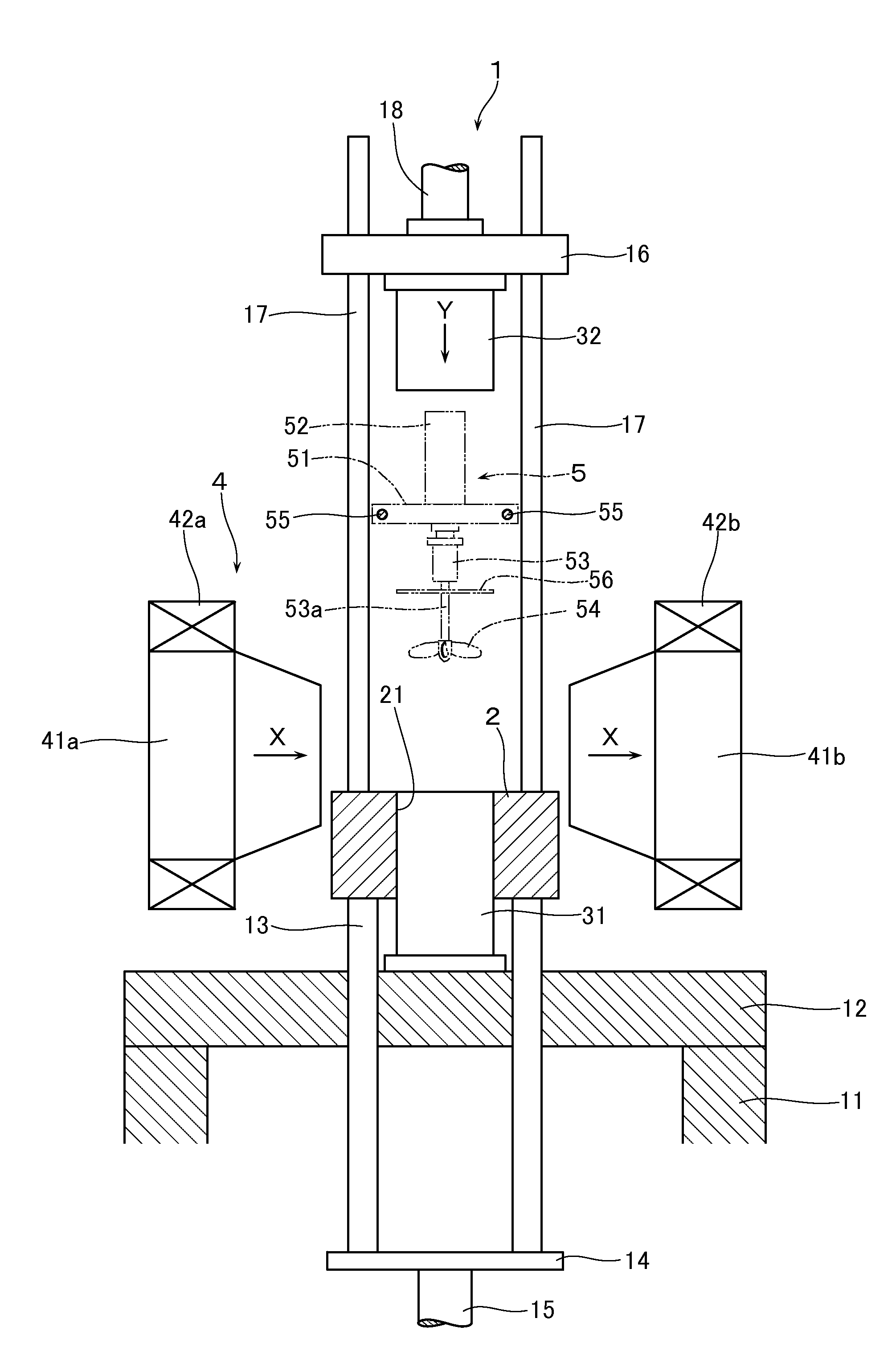
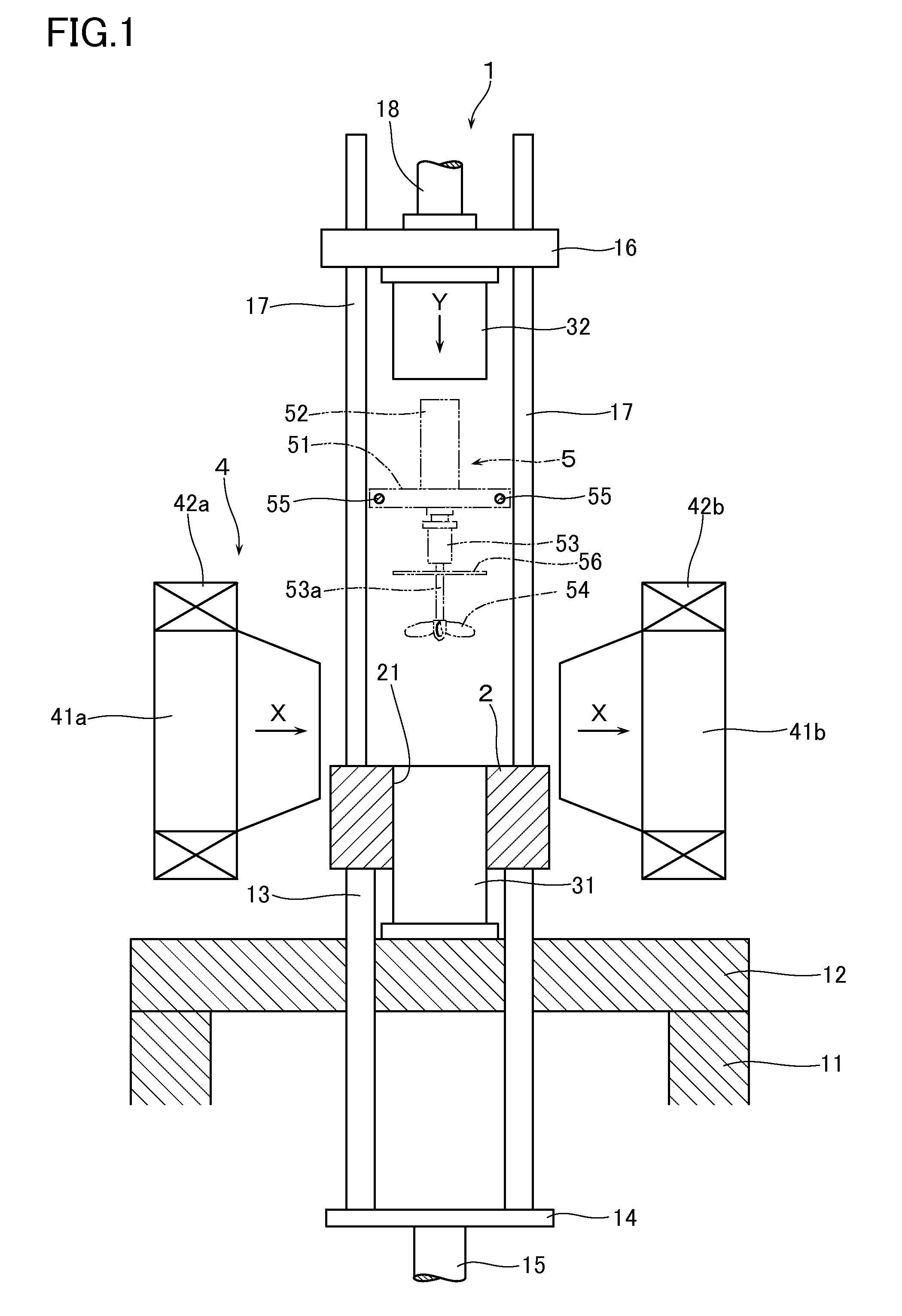
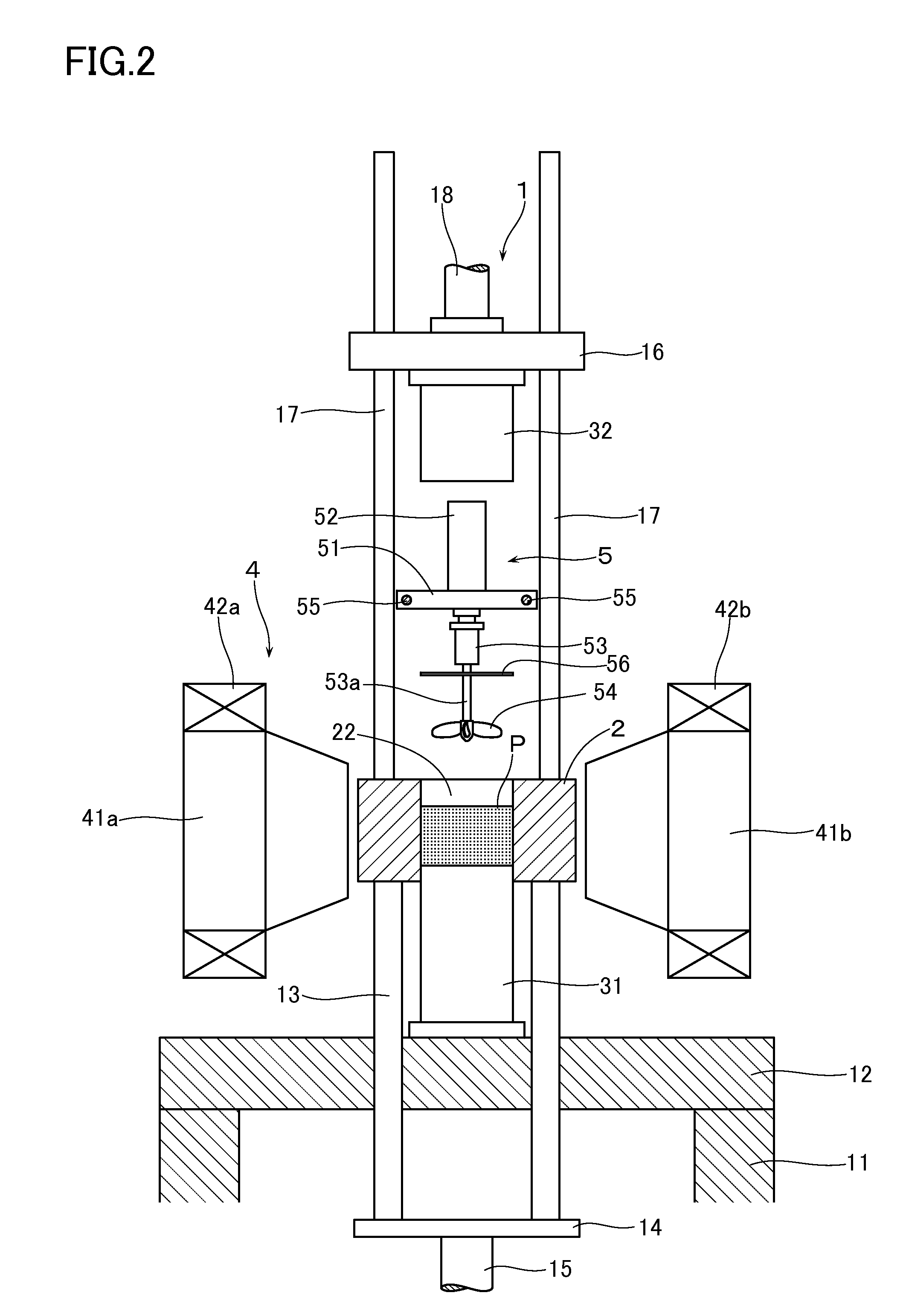
[0061]In the example 2 a Nd—Fe—B alloy raw meal powder was manufactured as described below and, by using the compression molding machine 1 as shown in FIG. 1, orienting step and the molding step were executed to manufacture a predetermined molded body. Thereafter, a sintering step was executed to sinter this molded body in vacuum atmosphere at a temperature of 1020° C. for 6 hours, thereby obtaining a Nd—Fe—B sintered magnet.
[0062]As the material for Nd—Fe—B permanent magnet, there was used a material whose composition is 25Nd-3Pr-1Dy-0.95B-1Co-0.2Al-0.05Cu-0.01Ga-0.05Mo-bal.Fe was used. After vacuum fusion, casting was made on water-cooled cupper roll to thereby manufacture into a foil band (strip) of 0.1 mm˜0.5 mm. This manufactured alloy raw material was once subjected to coarse grinding in hydrogen grinding step and subsequently subjected to fine grinding by a jet mill fine grinding step, thereby obtaining an alloy raw meal powder.
[0063]Further, the compression molding machine 1...
example 3
[0066]In the Example 3, alloy raw meal powder was manufactured in the same method as in the Example 2. By using the compression molding machine as shown in FIG. 1, agitation was executed in the same conditions as in the Example 2 while agitating in the magnetic field by the agitating apparatus 5 to thereby orient in the magnetic field. Thereafter, compression molding was executed and sintered in the same conditions as those in Example 2 to thereby obtain a sintered magnet. In this case, the molding pressure was set to 0.3 t / cm2 and the kind of magnetic field and the intensity of the magnetic field in the orienting step and the molding step were varied.
[0067]FIG. 11 is a table showing average values of the magnetic properties when respectively 100 sintered magnets were obtained by varying the kind of the magnetic field and the intensity of the magnetic field. According to this, it can be seen that, in magnetic pulse field, the orientation exceeded 95% at the peak magnetic field of ab...
PUM
| Property | Measurement | Unit |
|---|---|---|
| Fraction | aaaaa | aaaaa |
| Fraction | aaaaa | aaaaa |
| Fraction | aaaaa | aaaaa |
Abstract
Description
Claims
Application Information