Typical problems caused by heating of the
semiconductor junction and surrounding structure are: 1) failures brought on by such occurrences as non-homogenous distribution of the
current density over the junction (“
current crowding”), which causes a local hot spot in the
diode junction leading to early failure due to
thermal runaway; 2)
nucleation and growth of dislocations in the active region of the
diode in which the radiative recombination occurs due to the existence of an existing defect in the semiconductor crystalline structure and which is accelerated by heat; 3) degradation of materials utilized in the LED, such as
phosphor or encapsulate, causing loss of efficiency and changes in output color; and 4)
electromigration of
metal atoms at the metallization
layers of the diode causing growth of conductive “
whiskers” and early failure.
. . Heat generated by LED (sic) becomes the largest drawback in LED manufacturing industry, which causes different malfunctions to the circuitry.” U.S. Pat. No. 6,639,356 B2, col.
It does nothing to address the larger issue of dissipating heat away from the
package.
These means have met with limited success.
This is not an efficient means of heat removal.
In the case of LEDs, as the LED's capability to output light has increased over time, the power consumed by the LED has also increased.
The increase in power consumed by the LED results in a corresponding increase in
waste heat generated by the LED.
Passive cooling of a high powered LED does not remove a sufficient amount of heat to enable the LED to operate as efficiently as possible.
However, in the case of
high power LEDs, this method may not adequately remove the amount of heat necessary to achieve optimum LED performance.
This method may dissipate more heat when compared to passive
radiation of the electronic device
package alone; however, the heat dissipation achieved by using circuit boards with enhanced
thermal conductivity may still not be sufficient to enable the electronic device to achieve optimum performance.
. . a plurality of fins . . . . The fins have a large surface area to dissipate heat, which increases dissipation of heat from the
LED lamp, thereby increasing the amount of power that can be applied to the
LED lamp without damaging the
LED lamp, which in turn increases the amount of light that the LED lamp can produce.”) While conventional heat sinks allow for improved cooling when compared to cooling the electronic device without such a device, the cooling achieved by means of a conventional
heat sink may not be adequate to allow the electronic device to achieve optimum performance, particularly when a high powered LED is utilized.
Additionally, the increased bulk of the design added by a conventional
heat sink because of the need to maximize the surface area of the conventional
heat sink may be undesirable.
There are multiple significant problems involved with using a conventional electrical
direct current fan to cool an electronic device.
The conventional electrical
direct current fan may add an unwanted amount of bulk to the design.
Additionally, the use of a conventional electrical
direct current fan creates audible
noise which may be undesirable to the electronic device application.
Furthermore, the use of a fan to actively cool an electronic device may still not cool the electronic device sufficiently to achieve optimum performance of the electronic device.
Finally, the use of a fan may be undesirable because the fan must consume power to operate.
However, a piezo fan must consume power in order to provide any cooling benefit to the electronic device.
The use of a piezo fan may be undesirable because of this necessary
power consumption.
Additionally, piezo fans may be undesirable because of the increased bulk which they add to a design and the cooling obtained through the use of these fans may not be sufficient, particularly when used with
high power LEDs.
Under certain limited conditions, a Peltier element may result in significant cooling of the electronic device.
However, the Peltier element is extremely inefficient.
In fact, the Peltier element may consume up to twice as much power as it dissipates.
This increased power consumption is just one
disadvantage to using a Peltier element.
An additional
disadvantage is that because of the inefficiency of the Peltier element, a significantly larger heat sink must be used to dissipate the additional heat created by the Peltier element.
Furthermore, as the power transferred by the Peltier element increases, the temperature across the Peltier device tends to decrease; therefore, the use of a Peltier device may provide no cooling at all if the
system in which it is used is high powered.
The use of a
heat pipe may provide a more efficient method of removing heat from an electronic device when compared to some passive methods; however, there are still drawbacks to this type of cooling
system.
The use of a
heat pipe may be undesirable because the physical size of the
heat pipe must be large enough to allow space for the material to vaporize and move away from the heat source.
Additionally, the heat
pipe may not remove as much heat from the electronic device as is required to achieve optimum performance, particularly in the case of
high power LEDs.
In addition to the limited duration of such a solution, this solution is undesirable because it is not sustainable.
That is, when this kind of a material has been depleted, it cannot automatically be renewed.
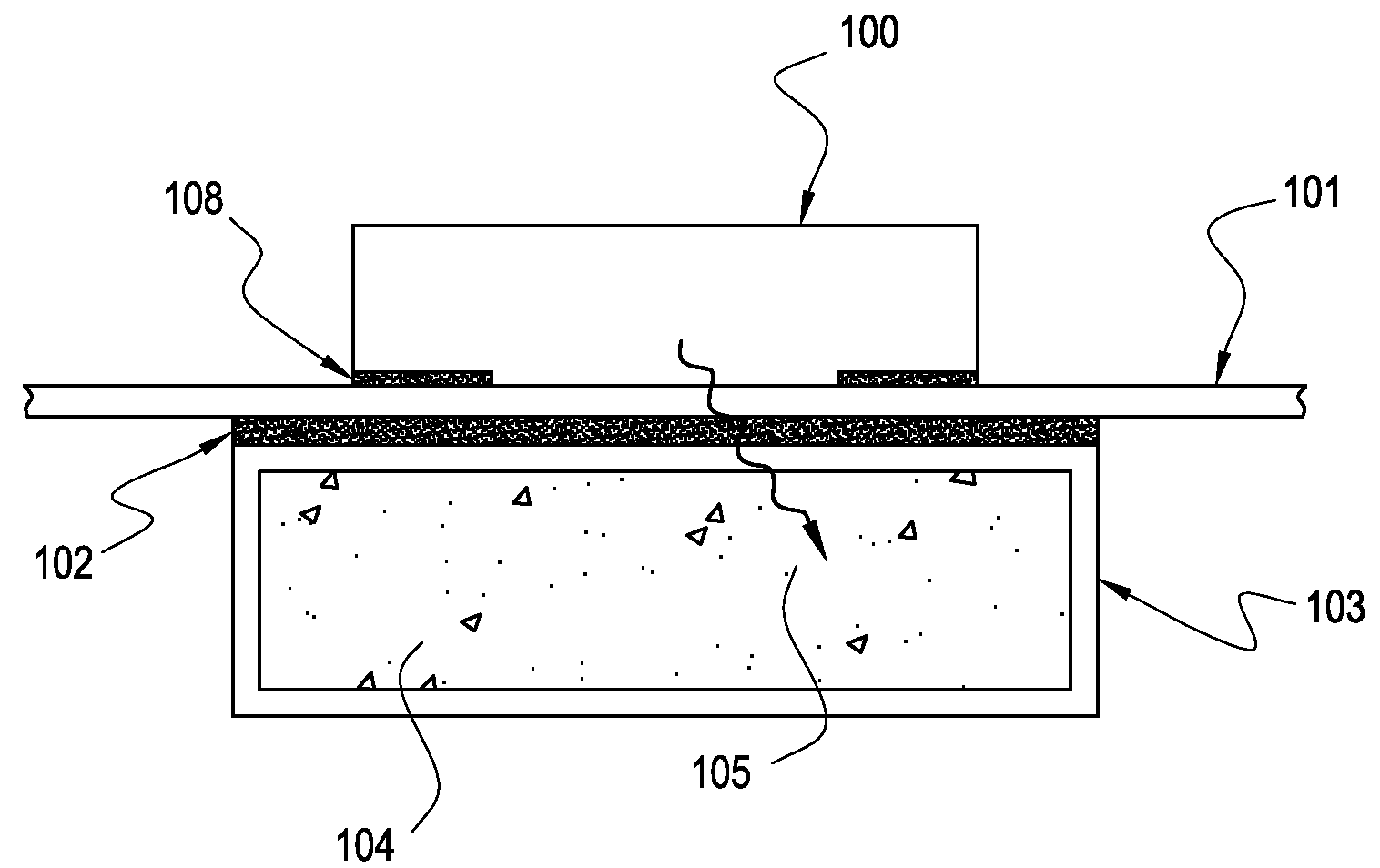
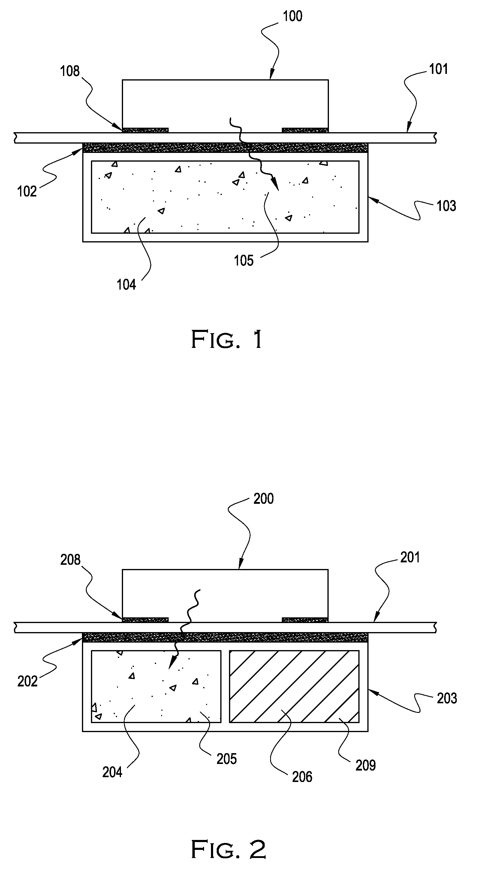
However, the invention of U.S. Pat. No. 6,202,739 B1 does not address the use of
phase change materials or other materials that may undergo endothermic reactions other than organic paraffin compounds, including n-eicosene, n-octadecan, and n-dotriacontane, low-temperature
solder alloy, and a low-temperature
metal, such as
gallium.
Furthermore, U.S. Pat. No. 6,452,217 B1 does not disclose the use of additional endothermic reactions, nor does it disclose the use of these materials in a form which is not embedded in a
metal component of some sort.
However, the invention of U.S. Pat. No. 5,508,884 does not disclose the use of any material other than
phase change liquid.
It is apparent from the aforementioned prior art that there is no known way to provide an efficient and sustainable means of sufficient heat removal from electronic devices without burdening the design with increased power consumption or bulk.
