Luminescent solar collector
a solar collector and solar energy technology, applied in the field ofluminescent solar collectors, can solve the problem that the wavelength of the fluorescent red 300 is poorly absorbed by the fluorescent red 300, and achieve the effect of increasing the amount of light energy
- Summary
- Abstract
- Description
- Claims
- Application Information
AI Technical Summary
Benefits of technology
Problems solved by technology
Method used
Image

Examples
example 1
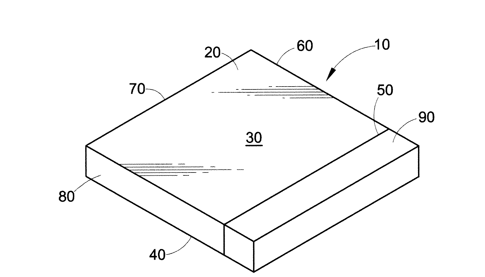
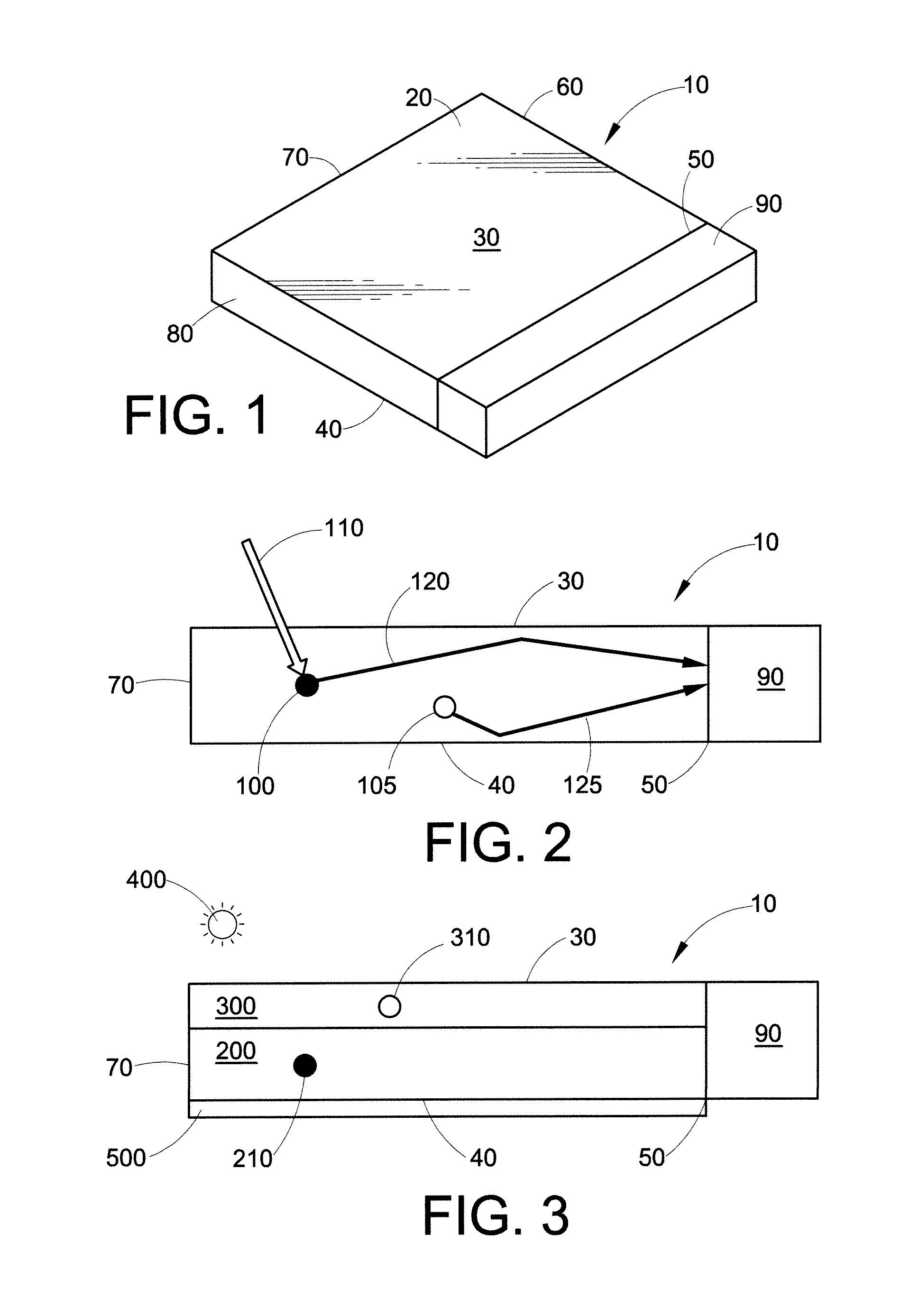
[0131]Lumogen® F Red 300 fluorescent dye was molded into plaques, and the plaques were tested for their edge emission output. Plaques were formed by mixing a polycarbonate with Lumogen® F Red 300 at loadings of 200 ppm and 500 ppm. The polycarbonate was a bisphenol-A homopolycarbonate having a weight average molecular weight of 60,000 versus polystyrene standards and a polydispersity of 2.1 to 2.3. The polycarbonate and dye were placed in a zip-lock polyethylene bag and shaken vigorously for about 3-4 minutes. The mixture was then extruded to produce pellets. The extruded pellets were dried in an oven at 120° C. for about 6 hours, then molded using an LTM-Demag molding machine into square plaques of 60 mm×60 mm, with 3.2 mm thickness.
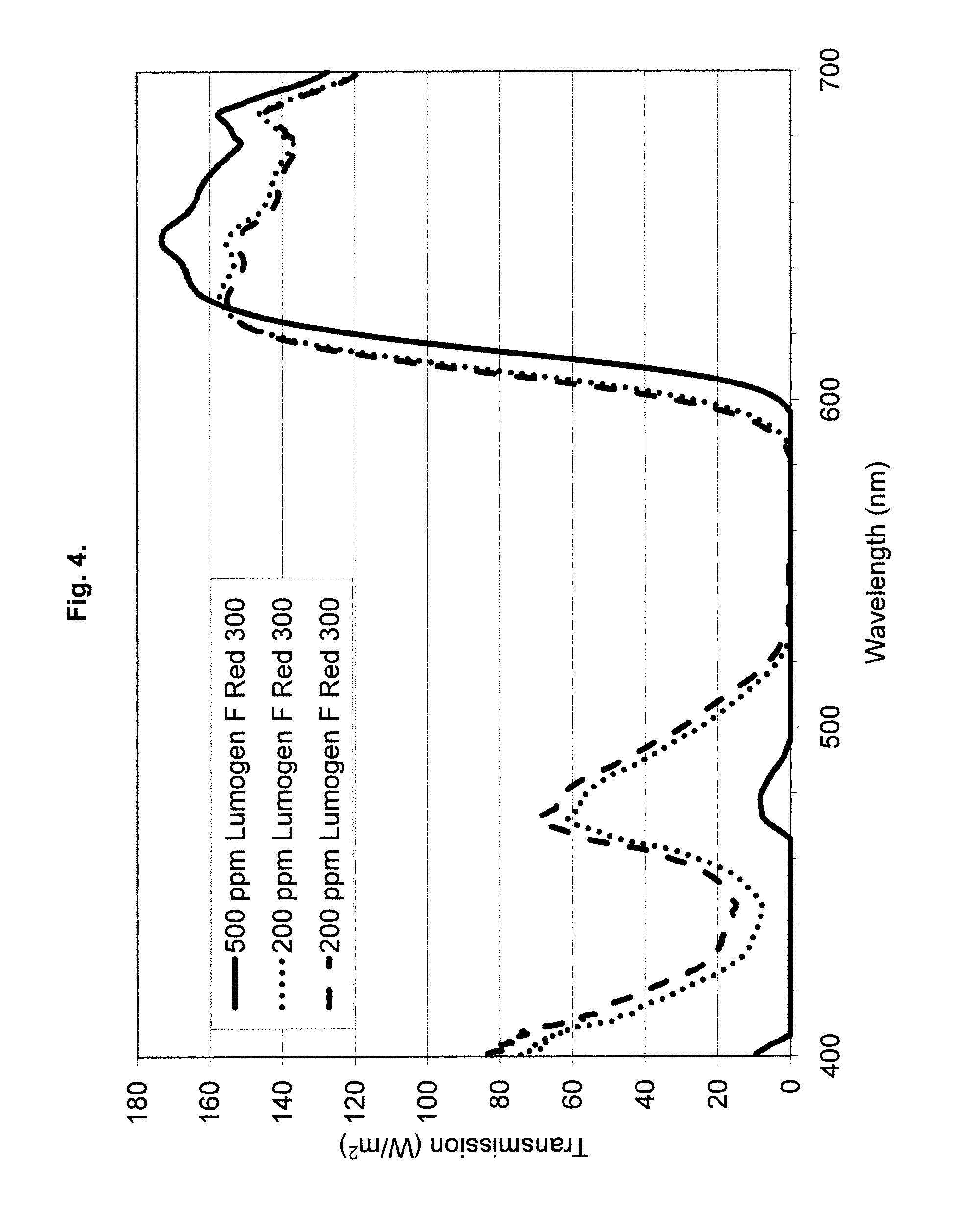
[0132]The plaques were placed under a solar simulator (1000 W / m2) and their transmission spectra were measured over a range of 400 nanometers to 1000 nanometers. FIG. 4 is a graph showing the transmission spectra of the plaques with 200 ppm loading comp...
example 2
[0133]Synthesis of Formula (IIb):
[0134]In a 250 mL round bottom flask perylene dianhydride (7.5 grams, 19.2 mmol), 18 mL water, 2,6-diisopropyl aniline (2.25 grams, 12.7 mmol), imidazole (38 grams, 558.2 mmol), and zinc acetate dihydrate (2.5 grams, 11.4 mmol) were mixed together and heated to 190° C. for 22 hours. The mixture was then cooled to room temperature. Next, 75 mL chloroform was added and the mixture was stirred again for 2 hours. The resulting slurry was filtered through a glass sinter funnel. The filtrate was concentrated and evaporated to dryness. The crude solid was then purified by silica gel column chromatography using a hexane-dichloromethane mixture (5 to 50 %), and the yield was 1.1 grams (˜11 %).
[0135]1H NMR (CDCl3): 8.70-8.67 (d, 2H), 8.52-8.47 (t, 4H), 7.96-7.94 (d, 2H), 7.70-7.66 (t, 2H), 7.53-7.48 (t, 1H), 7.38-7.36(d, 2H), 2.81-2.76 (m, 2H), 1.21 (s, 12H).
example 3
[0136]Plaques containing varying amounts of Lumogen® F Red 300 and the perylene dye of Formula (IIb) were made using the same method as in Example 1. For comparison, a plaque was also made containing Lumogen® F Red 300 and Solvent Yellow 114, another dye that had a maximum absorption wavelength around 480 nm. Solvent Yellow 114 has the structure:
[0137]Again, the plaques were placed under a solar simulator (˜1000 W / m2) and their transmission spectra were measured over a range of 400 nanometers to 1000 nanometers. Table 1 shows the results.
TABLE 1EdgeEmissionPlaqueComposition of dyes in the plaque(W / m2)1500 ppm Lumogen ® F Red 3003702200 ppm Lumogen ® F Red 300 +38050 ppm Formula (IIb)3200 ppm Lumogen ® F Red 300 +378100 ppm Formula (IIb)4200 ppm Lumogen ® F Red 300 +375150 ppm Formula (IIb)5200 ppm Lumogen ® F Red 300 +352200 ppm Formula (IIb)6200 ppm Lumogen ® F Red 300 +229200 ppm Solvent Yellow 1147100 ppm Lumogen ® F Red 300 +290100 ppm Formula (IIb)8200 ppm Lumogen ® F Red 30034...
PUM
| Property | Measurement | Unit |
|---|---|---|
| weight ratio | aaaaa | aaaaa |
| absorption wavelength | aaaaa | aaaaa |
| absorption wavelength | aaaaa | aaaaa |
Abstract
Description
Claims
Application Information