
Optical film and retardation sheet, and liquid crystal compound

a technology of optical film and retardation sheet, applied in the direction of optical elements, instruments, transportation and packaging, etc., can solve the problems of difficult to solve the above problems, complicated process for controlling optical directions, and difficult to arbitrarily control the wavelength dispersion by the method, etc., to achieve the effect of simple production process

Active Publication Date: 2010-02-25
FUJIFILM CORP
View PDF2 Cites 48 Cited by
  • Summary
  • Abstract
  • Description
  • Claims
  • Application Information

AI Technical Summary

Benefits of technology

[0008]For solving the problems above, the present invention contemplates for providing a novel polymerizable liquid crystal compound with reverse wavelength dispersion that can be produced in a simple preparative method, and providing a retardation sheet with reverse wavelength dispersion of its birefringence that can be produced in a simple production process by using the compound. Further, the present invention contemplates for providing a liquid crystal composition, a retardation sheet, and an elliptical polarizing plate, using the novel compound.
[0009]After intensive studies to solve the problems above, the inventors of the present invention have found that it is possible to give reverse dispersion of the wavelength dispersion in a film which is obtained by coating an oriented film with a particular material, followed by orienting and then immobilizing the thus-coated material. Thus, the inventors have attained to complete the present invention.

Problems solved by technology

However, generally, the wavelength dispersion of films is normal wavelength dispersion, in which the phase dispersion in longer wavelength region is normally smaller than the phase dispersion in shorter wavelength region, and thus, it is difficult to solve the problems above.
However, for producing the above retardation sheets, a complicated process is required for controlling the optical directions (optical axes and slow phase axes) of the two polymer films.
However, it is very difficult to control the wavelength dispersion arbitrarily by the method, because the mixed molecule is not liquid crystalline and thus, increase of the blending ratio leads to disappearance of liquid crystallinity.
However, the synthetic route for the compounds disclosed in JP-A-2005-289980 is relatively long, and thus, the method is not favorable, considering its production cost.

Method used


Image

  • Optical film and retardation sheet, and liquid crystal compound
  • Optical film and retardation sheet, and liquid crystal compound
  • Optical film and retardation sheet, and liquid crystal compound

Examples


example 1

Preparation of Exemplified Compound (2)

[0267]The Exemplified compound (2) was prepared, in accordance with the following scheme:

[0268]The synthesis of each of Compounds (2-1) to (2-3) was carried out in reference to the methods described in “Journal of Chemical Crystallography” (1997), 27(9), p. 515-526.

[0269]To 50 ml of a tetrahydrofuran solution of 8.5 g (0.1 mol) of cyanoacetic acid (2-4) and 14.4 g (0.1 mol) of 4-hydroxybutyl acrylate (2-5), 20.6 g (0.1 mol) of dicyclohexylcarbodiimide (DCC) was added dropwise under cooling on ice. The resultant mixture was warmed to room temperature and stirred at the same temperature for 2 hours, and the resultant solid matter was removed by filtration. The solvent in the filtrate was removed off by distillation under reduced pressure, and the resultant solid matter was removed by filtration, to give 18.6 g of Compound (2-6) (yield: 88 mol %).

[0270]A suspension of 15.7 g (50 mmol) of Compound (2-3), 12.7 g (60 mmol) of Compound (2-6), and 50 m...

examples 2 and 3

Preparation of Exemplified Compounds (1) and (3)

[0274]Exemplified compounds (1) and (3) were prepared in the same manner as in Example 1, except that 4-hydroxybutyl acrylate used in Example 1 was replaced with 2-hydroxyethyl acrylate or 4-hydroxybutyl methacrylate, respectively.

[0275]1H-NMR (CDCl3, 300 MHz):

[0276]0.75-1.25 (m, 36H), 1.40-1.65 (m, 4H), 1.65-2.00 (m, 12H), 2.10-2.25 (m, 4H), 2.45-2.60 (m, 2H), 4.40-4.55 (m, 4H), 5.92 (d, 1H), 6.20 (dd, 1H), 6.50 (d, 1H), 7.21 (d, 2H)

[0277]Mass (m / z, POSI) 863

[0278]1H-NMR (CDCl3, 300 MHz):

[0279]0.75-1.25 (m, 36H), 1.40-1.65 (m, 4H), 1.65-2.10 (m, 19H), 2.10-2.25 (m, 4H), 2.45-2.60 (m, 2H), 4.40-4.55 (m, 4H), 5.58 (d, 1H), 6.15 (d, 1H), 7.21 (d, 2H)

[0280]Mass (m / z, POSI)=905

example 4

Preparation of Exemplified Compounds (78) to (95)

[0281]Exemplified compounds (78) to (95) were prepared in the same manner as in Example 1. The structure of each of the thus-obtained compounds was identified in the same manner as in Examples 1 to 3, based on various spectroscopic data, such as the data of NMR spectrum and Mass spectrum.

[0282]The phase-transition temperatures of the respective compounds obtained in Examples 1 to 4 are shown in Table 1. In Table 1, “Cr” represents crystalline phase, “Ne” represents nematic phase, “Iso” represents isotropic phase, and “Col” represents columner phase, respectively. Numbers represent the phase transition temperatures in the course of heating.

TABLE 1Exemplified compoundPhase-transition temperature (° C.) (1)Cr 180 Ne 280 Iso (2)Cr 142 Ne 250 Iso(78)Cr 137 Ne 210 Iso(79)Cr 147 Ne 163 Iso(80)Col 102 Ne 135 Iso(81)Cr 119 Ne 153 Iso(82)Ne 114 Iso(83)Ne 124 Iso(84)Cr 170 Ne 200 Iso(85)Cr 108 Ne 143 Iso(86)Cr 107 Ne >180 Iso(87)Cr 170 Ne 206 Is...


PUM

PropertyMeasurementUnit
crystal compositionaaaaaaaaaa
optically anisotropicaaaaaaaaaa
transparentaaaaaaaaaa

Abstract

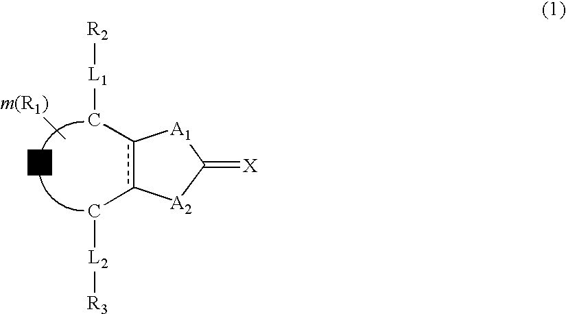
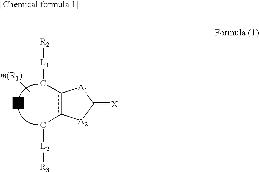
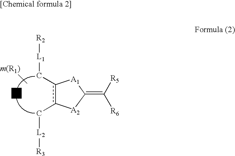
A compound of formula (1): wherein A1 and A2 are —O—, —NR—, —S—, or —CO—, in which R is a hydrogen atom or substituent; Z is one or two atoms selected from a carbon atom or a non-metal atom of Group 14, 15 or 16 in the Periodic Table, and forms a five- or six-membered ring with the C—C═C—C or C═C—C═C; R1, R2, and R3 each are a substituent; m is an integer of 0 to 4; L1 and L2 are a single bond or divalent linking group; X is a non-metal atom of Group 14, 15 or 16 in the Periodic Table, and may have a hydrogen atom or R4; and at least one of R, R1, R2, R3, and R4 is substituted with a polymerizable group; a liquid crystal composition, an optical film, a retardation sheet, a polarizing plate, and a liquid crystal display.

Description

TECHNICAL FIELD[0001]The present invention relates to a polymerizable compound with reverse wavelength dispersion (or reverse dispersion of wavelength dispersion), a polymerizable liquid crystal compound, and a polymerizable liquid crystal composition. Further, the present invention relates to an optical film carrying the liquid crystal compound immobilized therein. Further, the present invention relates to a retardation sheet (a phase difference plate) having reverse wavelength dispersion of birefringence, such as a broadband λ / 4 plate. Further, the present invention relates to a polarizing plate and a liquid crystal display each using the retardation sheet.BACKGROUND ART[0002]The wavelength plates (or wave plates) have been widely used for attaining high contrast ratios and improving color shift phenomena at wide view angles in color TFT liquid crystal displays of various kinds of display modes, and the like. For prevention of change in color or discoloration, it is needed to make...

Claims


Application Information

Patent Timeline
Patent Type & Authority Applications(United States)
IPC IPC(8): G02F1/1347G02F1/13C07C311/21C07C233/64
CPCC07D277/64C07D339/06C07D409/12C09K19/3491Y10T428/10C09K19/54C09K2019/0448G02B5/3016G02B5/3083C09K19/3497C09K2323/00
Inventor UEHIRA, SHIGEKIMATSUUMI, MICHITAKAMORISHIMA, SHINICHIICHIHASHI, MITSUYOSHIYASUDA, KOTAROTAKEUCHI, HIROSHI
Owner FUJIFILM CORP
Learn More