Particle counter and particle counting device having particle counter, and particle counting system and its use method

Inactive Publication Date: 2010-02-25
NIDEC SANKYO CORP
View PDF9 Cites 22 Cited by
  • Summary
  • Abstract
  • Description
  • Claims
  • Application Information

AI Technical Summary

Benefits of technology

[0085]As described above, according to at least an embodiment of the present invention, suction of a fluid to be measured per unit volume can be performed in a shorter period of time at less cost than a conventional particle counter, resulting in a shorter measuring time. Accuracy of the measuring results can also be prevented from being degraded. Further, because a plurality of particle counting devices are used, even when one of the particle counting devices becomes out of order, the particle measurement can be continued by the other particle counting devices.
[0086]At least an embodiment of present invention comprises a light source for emitting laser light, a projection lens system for condensing the laser light onto a sample fluid, a light-receiving lens system for condensing scattered light generated by irradiating the particles in the sample

Problems solved by technology

In the above-mentioned particle counter, a data input terminal and a display section for displaying results of computations, etc. are installed in the measuring control section that controls the measuring section; therefore, the entire device is oversized and expensive because of complicated computations such as the computation of particle size distribution.
Therefore, within the observation environment, for example, inside a clean room, it is necessary to make observations at a plurality of locations; however, an extremely expensive investment is required in order to place a plurality of devices for observing the particle counters.
Because of this, cleanliness at a plurality of measuring locations cannot be constantly and simultaneously monitored.
Also, according to the above-mentioned measuring method, there is an assumption in the process of converting the counting value into a value per unit volume that “the obtained counting value, even the one obtained at any time during the measurement, is invariable”; consequently, the measuring result may contain great error.
In such a case, accuracy of the measuring result is degraded.
One may attempt to shorten the measuring time by enhancing the suction of a fluid to be measured; however, this method requires the improvement of the capability of the measuring section to enhance the suction of a fluid to be measured, thus increasing cost of the measuring section.
In such a case, a particle counting device is moved to each location to measure cleanliness sporadically because the installation of a plurality of expensive particle counting devices at multiple locations increases c

Method used


Image

  • Particle counter and particle counting device having particle counter, and particle counting system and its use method
  • Particle counter and particle counting device having particle counter, and particle counting system and its use method
  • Particle counter and particle counting device having particle counter, and particle counting system and its use method

Examples


first embodiment

(Overall Configuration)

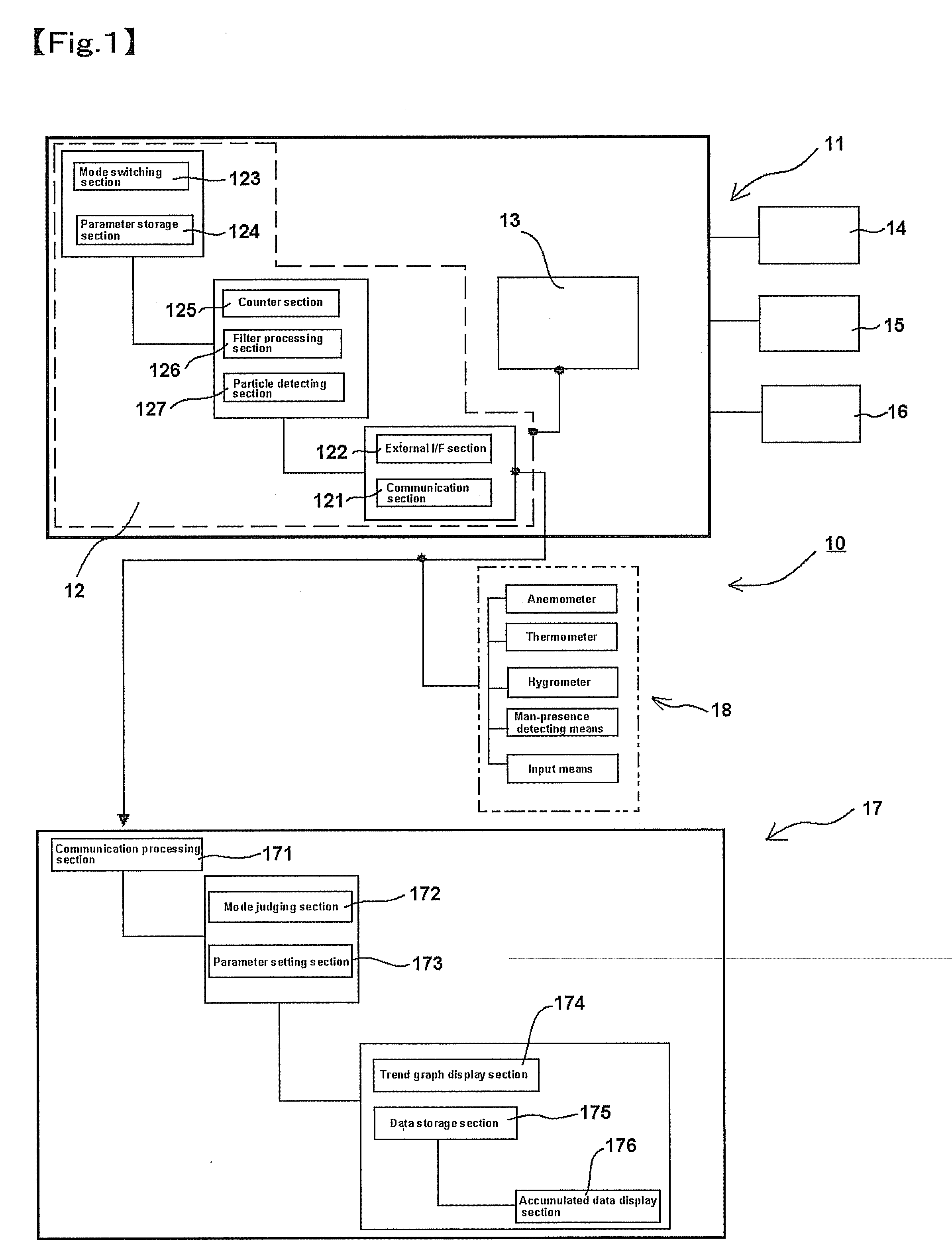
[0114]FIG. 1 is a block diagram showing a particle counter of at least an embodiment of the present invention and a particle counting device equipped with it. Note that, more specifically, it is a block diagram of a particle counting device equipped with a measuring device.

[0115]A particle counting device 10 is configured mainly by a particle counter 11 that can be permanently placed at an observation-necessary point, an information processing device 17 connected to the particle counter 11 for generating measuring data and displaying and processing the detection data, and other measuring devices, other than the particle counter, for measuring wind velocity, temperature, humidity, etc. Note that the observation-necessary location may be single or plural.

(Configuration of Particle Counter)

[0116]The particle counter 11 is a device for detecting and counting particles in a fluid to be measured, which comprises a measuring section 13 for detecting particles and a c...

second embodiment

[0141]The best form of at least another embodiment of the present invention is described hereinafter referring to the drawings. Note that the same codes are given to the same components as in the above-mentioned first embodiment.

[0142]FIG. 6 is a block diagram showing a configuration of a particle counting system 100 of the at least second embodiment of the present invention.

[0143]In FIG. 6, the particle counting system 100 has a plurality of particle counters 11, the information processing device 17, the power source device 14, the suction pump 15, and the alarm 16. Note that since the plurality of particle counters 11 share the same configuration, only one of the particle counters 11 is enlarged for explanation. To each of the other particle counters 11 of which the illustration of the internal configuration is omitted, the suction pump 15 (not illustrated) is connected respectively. In the above-mentioned first embodiment, the device having the particle counter 11, the informatio...

third embodiment

[0163]The configuration of at least an embodiment of the present invention is described in detail hereinafter based on the best form of an embodiment shown in the figures.

(Overall Configuration)

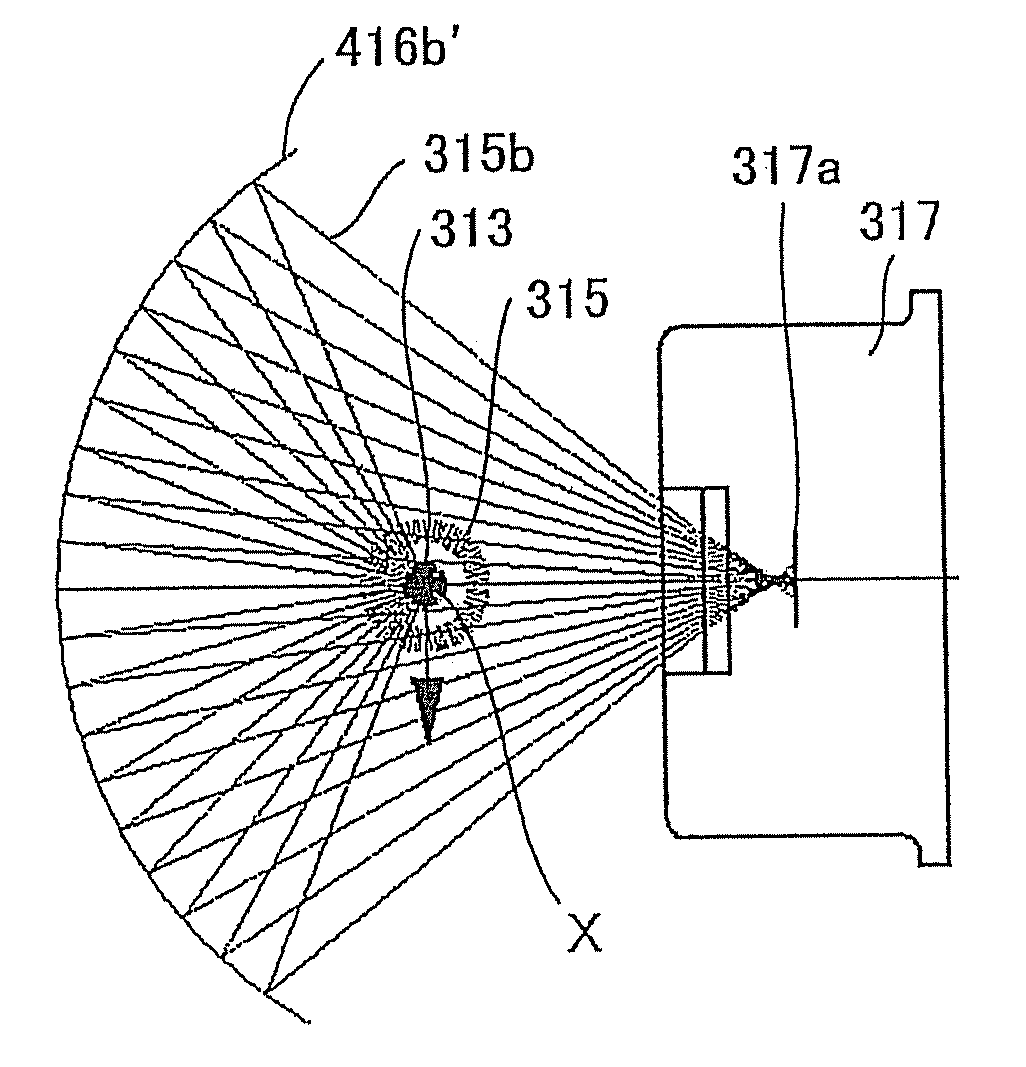
[0164]FIG. 10(A) is a plan view of a particle counter of at least an embodiment of the present invention; (B) is its side view. Note that in this embodiment, a particle counter is a light-scattering particle counter that measures the number of airborne particles by using a light scattering property and described hereinafter as “a light-scattering particle counter”.

[0165]A light-scattering particle counter 301 is provided with a light source 311 for emitting laser light 312, a projection lens system 314 for condensing the laser light 312 onto a sample fluid 313, a light-receiving lens system 316 for condensing the scattered light 315 generated by irradiating particles 313a present in the sample fluid 313 with the laser light 312, and a photo detector 317 for detecting the condensed scattered l...


PUM


Abstract

A particle counting device 11 for detecting and counting particles in a fluid to be measured comprises a measuring section 13 for detecting particles and a control section 12 for processing the output signal from the measuring section 13. When an abnormality occurs, a signal to issue a warning is generated. With this, a constant monitoring or observation is possible. Also, a particle counting system comprising a plurality of particle counting devices 11 and an information processing device 17 for processing the results of the counting by the particle processing devices 11 is also provided. The plurality of particle counting devices 11 are electrically connected to the information processing device 17 in multiple and in parallel. Alternately, a particle counting system comprising a plurality of particle counting devices 11 for detecting and counting particles in a fluid to be measured is also provided. To one of the plurality of particle counting devices 11, the other particle counting devices 11 are electrically connected in multiple and in parallel. Therefore, a particle counting system, the measurement time of which can be shortened while maintaining the accuracy of the measurement results, and its use method are provided relatively inexpensively.

Description

CROSS REFERENCE TO RELATED APPLICATIONS [0001]This is a U.S. national stage of application No. PCT / JP2006 / 323746, filed on Nov. 28, 2006. Priority under 35 U.S.C. §119(a) and 35 U.S.C. §365(b) is claimed from Japanese Application No. 2005-344645, filed Nov. 29, 2005; Japanese Patent Application No. 2005-343221, filed Nov. 29, 2005; Japanese Application No. 2005-374041, filed Dec. 27, 2005; Japanese Application No. 2006-020464, filed Jan. 30, 2006; and Japanese Application No. 2006-041064, filed Feb. 17, 2006, the disclosures of which are also incorporated herein by reference.TECHNICAL FIELD [0002]The present invention relates to a particle counter for detecting and counting particles in a fluid to be measured, a particle counting device equipped with it, a particle counting system and its use method.BACKGROUND [0003]For manufacturing semi-conductor devices and liquid crystal panel devices, the environment of a clean room or clean booth is an important factor to determine the yield o...

Claims


Application Information

Patent Timeline
IPC IPC(8): G01N21/00G06F19/00G08B21/00
CPCG01N15/14G01N2035/009G01N35/00613
Inventor TSUNETA, HARUHIROSUGIOKA, EIICHITONOUCHI, HIROSHISHIOZAWA, JUNICHIHAYASHI, KENICHIMOMOSE, TETSUOFURIHATA, HIROAKI
Owner NIDEC SANKYO CORP
Why Eureka
Try Eureka