
Method of forming openings in selected material

a technology of selected materials and openings, applied in the field of device fabrication, can solve the problems of high cost of equipment, complex manufacturing processes currently formulated for thin film devices, and inability to meet the requirements of semiconductor device fabrication methods, and achieve the effect of smaller permeable areas

Inactive Publication Date: 2010-02-25
NEWSOUTH INNOVATIONS PTY LTD
View PDF5 Cites 10 Cited by
  • Summary
  • Abstract
  • Description
  • Claims
  • Application Information

AI Technical Summary

Benefits of technology

[0015]When reversing the permeability of the resist in an area, the reversal need not be complete. Controlling the reversal process, to achieve a partial reversal of the permeability, provides an excellent method of reducing the area made permeable and hence reducing the hole size made in the underlying selected material when etching through the permeable area.
[0017]a) applying carefully measured amounts of resist over the plasticised areas such that the plasticiser diffuses from the plasticised area into the newly deposited resist and causes reduced permeability particularly around the edges of the plasticised region;
[0018]b) applying a solvent for the resist which softens and reflows the resist in the plasticised regions increasing the mobility of the plasticiser and allowing diffusion of the plasticiser over a larger area resulting in a reduction of permeability particularly at the edges of the original plasticised areas
[0019]c) heating the resist to cause softening of the resist which increases the mobility of the plasticiser in the plasticised regions and causes diffusion of the plasticiser over a larger area resulting in a reduction of permeability particularly at the edges of the original plasticised areas
[0023]When applying resist to the surface to be etched, the thickness of the resist may be varied so that the thinner regions will become permeable to the etching solution prior to the thicker regions after application of a given amount of the plasticiser solution. This will also provide additional ways of making the feature sizes (permeable areas) smaller than can be achieved by using the standard droplet size. Because the plasticised region diminishes in area with depth in the resin (polymer resist) layer the thicker the resin layer the smaller the area of the plasticised region will be at the surface of the selected material to be etched.
[0025]Subsequent deposition of the first solution in target locations can therefore produce permeable regions of reduced area compared to the droplet size by virtue of the fact that some of the area under each droplet has resist that is thicker.

Problems solved by technology

However, the efficiencies obtained for such devices are significantly lower than those obtained for silicon-wafer-based solar cell devices.
In addition, the manufacturing processes currently formulated for thin film devices are still complex and require significant improvement for cost-efficient production on larger scales.
However, semiconductor device fabrication methods require costly equipment (e.g., lasers, mask aligners), expensive clean room environments, and generally many time-consuming steps.
A further disadvantage of current photolithographic patterning methods is that if a number of different metal contact patterns are required, then the entire photolithographic process must typically be repeated for each pattern.
However, making metal contact to p-type silicon from the same surface requires etching of both the dielectric layer and the n-type silicon layer located directly under the dielectric layer.
Consequently, it is difficult to use a single photolithographic process to create holes or grooves for both sets of contacts.

Method used


Image

  • Method of forming openings in selected material
  • Method of forming openings in selected material
  • Method of forming openings in selected material

Examples


Embodiment Construction

[0058]The following description is given by way of illustration only and shall not be taken as being in any way limiting as to the spirit or scope of the invention. Referring to the drawings, like numerals designate corresponding parts where possible throughout the several figures.

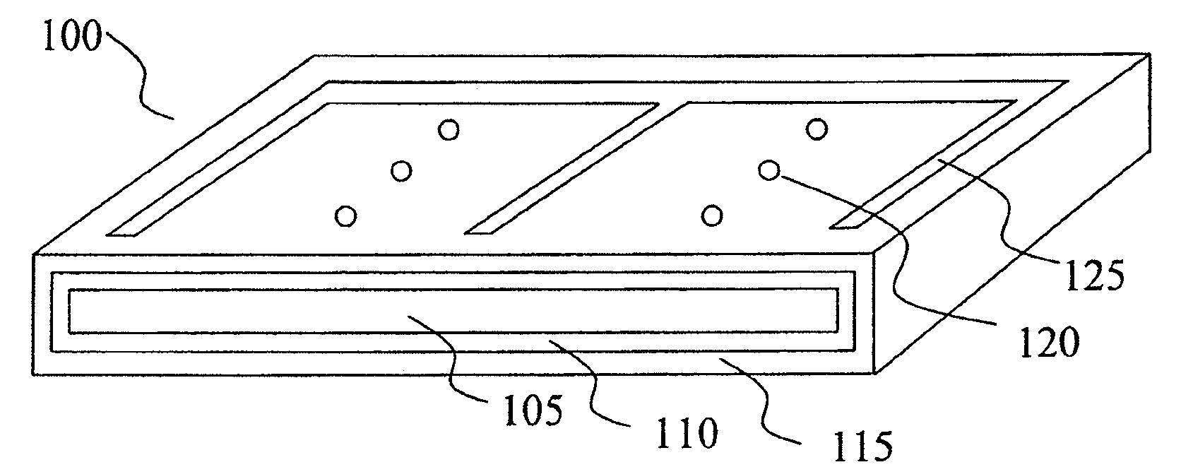
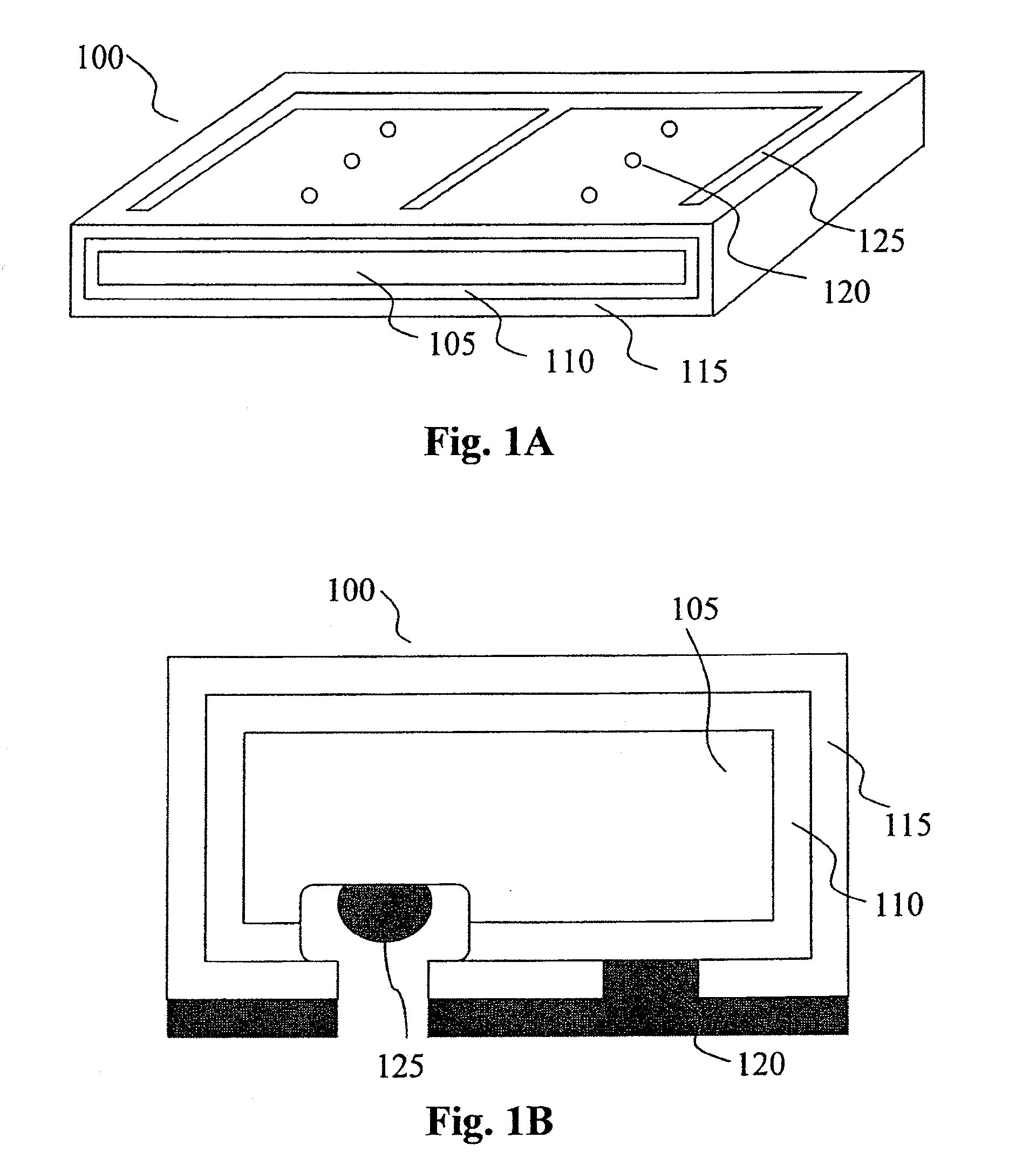
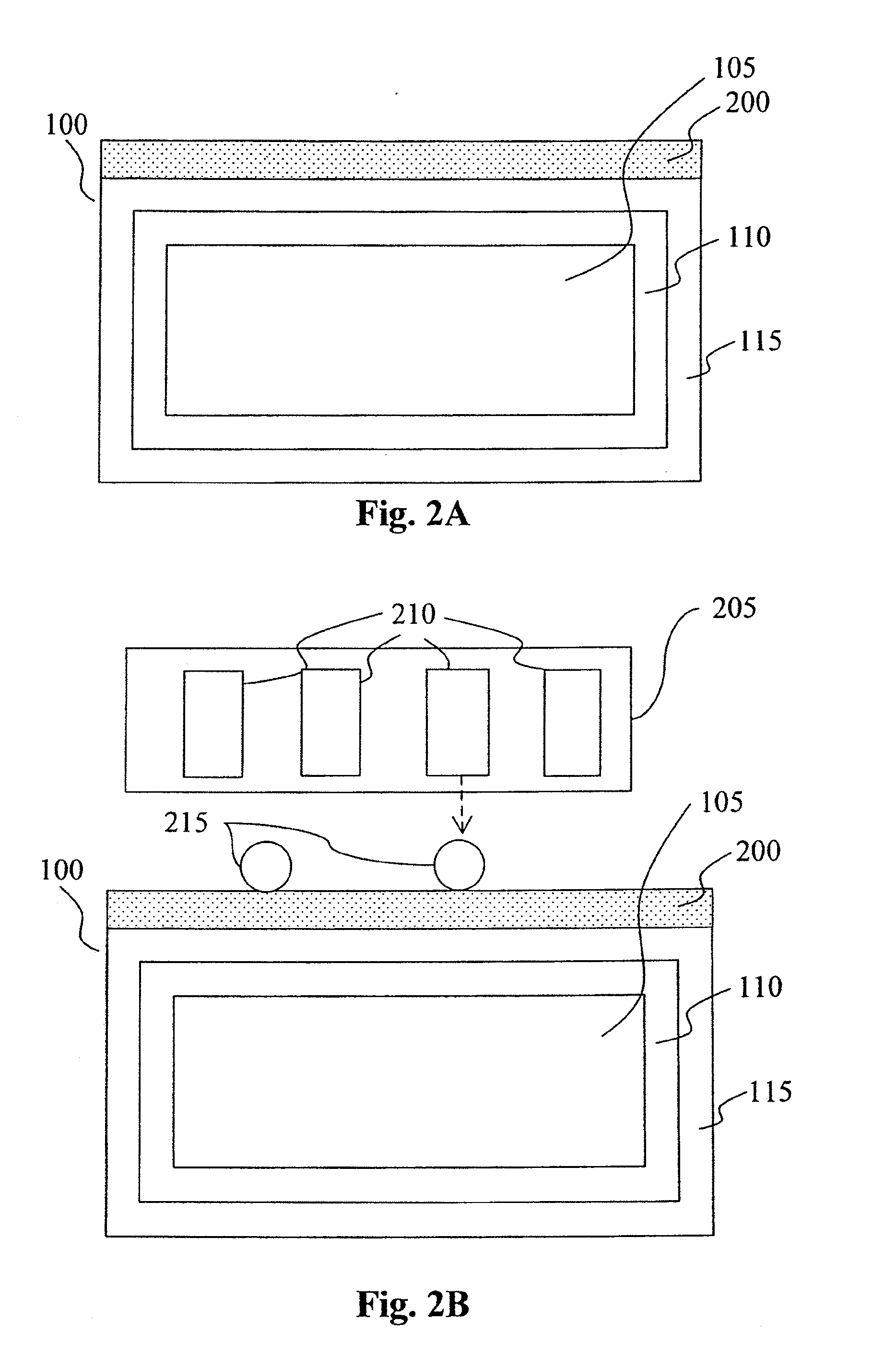
[0059]A method for forming openings, such as circular holes and continuous grooves, in structures or layers of devices is described below. The openings, once formed, can be used to facilitate metal contacting for the device. The described methods are preferably used in the fabrication of semiconductor devices, such as solar cell devices. However they can also be advantageously utilised in the fabrication of micro-electro-mechanical systems (MEMS) devices. The method of forming the openings requires the use of a resist (or resin) layer which is formed over the device substrate. The resist layer is then patterned by the selective deposition of small liquid drops onto the resist surface. The deposited liquid ...


PUM

PropertyMeasurementUnit
Thicknessaaaaaaaaaa
Dielectric polarization enthalpyaaaaaaaaaa
Structureaaaaaaaaaa

Abstract

A method is provided for forming an opening in a layer of a selected material. The method comprises, forming a polymer resist layer over said selected material and plasticising areas of the resist where openings are to be formed. The plasticising is performed by depositing a first solution onto the surface of said polymer resist layer, where the first solution is a plasticiser selected to increase permeability of the polymer resist layer to a second solution, in an area which has absorbed the first solution. The second solution is selected to be an etchant or solvent for the selected material. After the resist layer has been selectively plasticised, it is contacted with the second solution, which permeates the polymer resist layer in the area of increased permeability and forms an opening in the selected material.

Description

INCORPORATION BY REFERENCE[0001]This application is a continuation-in-part of International application No. PCT / AU2008 / 000023, filed Jan. 10, 2008, designating the U.S., and claiming priority to Australian application No. 2007900451, filed Jan. 31, 2007 and Australian application No. 2007904726, filed Jan. 31, 2007.[0002]Any foregoing applications, and all documents cited therein or during their prosecution (“application cited documents”) and all documents cited or referenced in the application cited documents, and all documents cited or referenced herein (“herein cited documents”), and all documents cited or referenced in herein cited documents, together with any manufacturer's instructions, descriptions, product specifications, and product sheets for any products mentioned herein or in any document incorporated by reference herein, are hereby incorporated herein by reference, and may be employed in the practice of the invention.COPYRIGHT NOTICE[0003]A portion of the disclosure of ...

Claims


Application Information

Patent Timeline
IPC IPC(8): G03F7/20
CPCB81C1/00087H01L31/18H01L31/04G03F7/42H01L21/47H01L21/47573H01L21/47635
Inventor WENHAM, STUART ROSSLENNON, ALISONUTAMA, ROLAND YUDADIBRATAHO-BAILLIE, ANITA WING YI
Owner NEWSOUTH INNOVATIONS PTY LTD
Learn More